Transcription of TECHNIQUES FOR MEASURING RESISTIVITY FOR MATERIALS ...
1 TECHNIQUES FOR MEASURING RESISTIVITY FOR MATERIALS CHARACTERIZATION 4200A-SCS PARAMATER ANALYZER APPLICATIONS | 1 TECHNIQUES FOR MEASURING RESISTIVITY FOR MATERIALS CHARACTERIZATION APPLICATIONS GUIDECONTENTSR esistivity Measurements of Semiconductor MATERIALS Using the 4200A-SCS Parameter Analyzer and a Four-Point Collinear Probe ..3van der Pauw and Hall Voltage Measurements with the4200A-SCS Parameter Analyzer ..8 Which Kelvin method is right for your RESISTIVITY measurements? The two application notes in this MATERIALS characterization applications guide offer tips and TECHNIQUES for choosing between the Four-Point Collinear Probe or van Der Pauw methods based on the type, shape, and thickness of your material and the magnitude of its | | 3 IntroductionElectrical RESISTIVITY is a basic material property that quantifies a material s opposition to current flow; it is the reciprocal of conductivity.
2 The RESISTIVITY of a material depends upon several factors, including the material doping, processing, and environmental factors such as temperature and humidity. The RESISTIVITY of the material can affect the characteristics of a device of which it s made, such as the series resistance, threshold voltage, capacitance, and other the RESISTIVITY of a material is common in both research and fabrication environments. There are many methods for determining the RESISTIVITY of a material, but the technique may vary depending upon the type of material, magnitude of the resistance, shape, and thickness of the material. One of the most common ways of MEASURING the RESISTIVITY of some thin, flat MATERIALS , such as semiconductors or conductive coatings, uses a four-point collinear probe.
3 The four-point probe technique involves bringing four equally spaced probes in contact with a material of unknown resistance. A DC current is forced between the outer two probes, and a voltmeter measures the voltage difference between the inner two probes. The RESISTIVITY is calculated from geometric factors, the source current, and the voltage measurement . The instrumentation used for this test includes a DC current source, a sensitive voltmeter, and a four-point collinear simplify measurements, the 4200A-SCS Parameter Analyzer comes with a project that contains tests for making RESISTIVITY measurements using a four-point collinear probe. The 4200A-SCS can be used for a wide range of material resistances including very high resistance semiconductor MATERIALS because of its high input impedance (>1016 ohms).
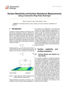
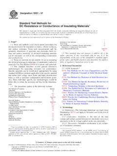
4 This application note explains how to use the 4200A-SCS with a four-point collinear probe to make RESISTIVITY measurements on semiconductor Four-Point Collinear Probe MethodThe most common way of MEASURING the RESISTIVITY of a semiconductor material is by using a four-point collinear probe. This technique involves bringing four equally spaced probes in contact with a material of unknown resistance. The probe array is placed in the center of the material, as shown in Figure 1. VSemiconductor Wafer4-PointCollinear ProbeSource currentfrom 1 to 4 Measure voltagebetween 2 and 3 LOHI1234 LOHIF igure 1. Four-point probe RESISTIVITY test circuitThe two outer probes are used for sourcing current and the two inner probes are used for MEASURING the resulting voltage drop across the surface of the sample.
5 The volume RESISTIVITY is calculated as follows: V = ____ __ t k ln 2 Iwhere: = volume RESISTIVITY ( -cm) V = the measured voltage (volts) I = the source current (amperes) t = the sample thickness (cm) k* = a correction factor based on the ratio of the probe to wafer diameter and on the ratio of wafer thickness to probe separation* The correction factors can be found in standard four-point probe RESISTIVITY test procedures such as SEMI MF84-02 Test Method for MEASURING RESISTIVITY of Silicon Wafers with an In-Line Four-Point Probe. RESISTIVITY Measurements of Semiconductor MATERIALS Using the 4200A-SCS Parameter Analyzer and a Four-Point Collinear Probe4 | Measurements of Semiconductor MATERIALS Using the 4200A-SCS Parameter Analyzer and a Four-Point Collinear ProbeAPPLICATIONS GUIDEFor some MATERIALS such as thin films and coatings, the sheet resistance, or surface RESISTIVITY , is determined instead, which does not take the thickness into account.
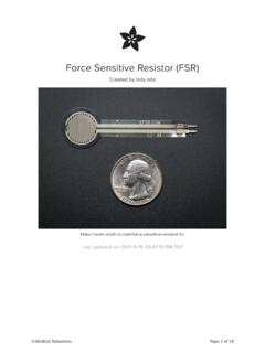
6 The sheet resistance ( ) is calculated as follows: V V = ____ ___ k = ___ k ln2 I Iwhere: = the sheet resistance ( /square or just )Note that the units for sheet resistance are expressed in terms of /square in order to distinguish this number from the measured resistance (V/I).Using the Kelvin Technique to Eliminate Lead and Contact ResistanceUsing four probes eliminates measurement errors due to the probe resistance, the spreading resistance under each probe, and the contact resistance between each metal probe and the semiconductor material. Figure 2 is another representation of the four-point collinear probe setup that shows some of the circuit = Lead ResistanceRC = Contact ResistanceRS = Sample ResistanceV = Measured Voltage Between Probes 2 And 3 Only the voltage drop due to RS2 is measured by the Current HIHILOLORL1RL2RL3RL4RC1RS2RS1RS3 VRC2RC3RC4 VFigure 2.
7 Test setup showing circuit resistancesThe RL terms represent the test lead resistance. RC represents the contact resistance between the metal probe and the semiconductor material. The contact resistance can be several hundred to a thousand times higher than the resistance of the sample material, which is represented by that the current flows through all the resistances in the first and fourth set of leads and probes, as well as through the semiconductor material. However, the voltage is only measured between probes 2 and 3. Given that between probes 2 and 3, the current only flows through RS2, only the voltage drop due to RS2 will be measured by the voltmeter. All the other unwanted lead (RL) and contact (RC) resistances will not be the 4200A-SCS to Make Four-Point Probe Collinear Probe MeasurementsThe 4200A-SCS comes with a project that is already configured for automating four-point probe RESISTIVITY measurements.
8 The project, Four-Point Probe RESISTIVITY Project, can be found in the Project Library in the Select view by selecting the MATERIALS filter. This project has two tests: one measures the RESISTIVITY using a single test current and the other measures the RESISTIVITY as a function of a current sweep. These two tests, Four-Point Probe RESISTIVITY measurement (4-pt-collinear) and Four-Point Probe RESISTIVITY Sweep (4-pt- RESISTIVITY -sweep), can also be found in the Test Library and can be added to a project. A screen capture of the Four-Point Probe RESISTIVITY measurement test is shown in Figure projects and tests included with the 4200A-SCS are configured to use either three or four SMUs (Source Measure Units).
9 When using three SMUs, all three SMUs are set to Current Bias (voltmeter mode). However, one SMU will source current (pin 1 of probe) and the other two (pins 2 and 3 of probe) will be used to measure the voltage difference between the two inner probes. An example of how this is set up with the 4200A-SCS is shown in Figure 4. One SMU (SMU1) and the GNDU (ground unit) are used to source current between the outer two probes. The other SMUs (SMU2 and SMU3) are used to measure the voltage drop between the two inner configuring the tests, enter an appropriate test current for SMU1. This will depend on the RESISTIVITY of the sample. For higher resistance samples, additional Interval time may need to be added in the Test Settings pane to ensure a settled | 5 RESISTIVITY Measurements of Semiconductor MATERIALS Using the 4200A-SCS Parameter Analyzer and a Four-Point Collinear ProbeAPPLICATIONS GUIDEF igure 3.
10 Screen Capture of Four-Point Probe RESISTIVITY measurement Test in the Clarius softwareUsing the Formulator,calculate the voltagedifference betweenSMU2 and : Set toCurrent Bias (VMU) Set current levelto have about a10mV drop betweenSMU2 and HISMU2: Set toCurrent Bias (VMU) Use as high impe-dance voltmeter,and set current to0A on 1nA HISMU3: Set toCurrent Bias (VMU) Use as high impe-dance voltmeter,and set current to0A on 1nA HIGNDU: Commonconnection for allSMUs. Or, this canbe SMU4 set HIFigure 4. SMU Instrument Designation for Four-Point Collinear Probe Measurement6 | Measurements of Semiconductor MATERIALS Using the 4200A-SCS Parameter Analyzer and a Four-Point Collinear ProbeAPPLICATIONS GUIDEThe Formulator in the Test Settings pane includes equations to derive the RESISTIVITY as shown in Figure 5.