Transcription of Understanding Soil Resistivity Testing - AEMC
1 Technical Hotline: (800) Technical Hotline: (800) Understanding Soil Resistivity TestingEffects of Soil Resistivity on Ground Electrode ResistanceFactors Affecting Soil ResistivityAPPLICATION NOTES | MAY 2019 Technical Assistance (800) 343-1391 Understanding Soil Resistivity TestingSoil Resistivity measurements have a threefold purpose. First, data is used to make sub-surface geophysical surveys as an aid in identifying ore locations, depth to bedrock and other geological phenomena. Second, Resistivity has a direct impact on the degree of corrosion in underground pipelines. A decrease in Resistivity relates to an increase in corrosion activity and therefore dictates the protective treatment to be used.
2 Third, soil Resistivity directly affects the design of a grounding system, and it is to that task that this discussion is directed. When designing an extensive grounding system, it is advisable to locate the area of lowest soil Resistivity in order to achieve the most economical grounding accomplish this task you need a ground resistance test instrument capable of Testing using four electrodes commonly referred to as a four point or four pole tester. You also need four auxiliary electrodes and four spools of wire. Next you need to decide on which test method to employ. There are two methods that are commonly used, the Wenner and the Schlumberger. Of these two, the Wenner method is the more popular and easier to use for Testing soil Resistivity for a grounding electrode system.
3 The Schlumberger method is more practical to use when the task is to plot soil Resistivity at several different depths, a requirement popular with geological surveying. In either method the results are represented by the Greek letter Rho ( ) and are expressed in Ohm-Meters or Ohm-Centimeters representing the resistance of a cubic meter of soil. For this application note we will concentrate on the Wenner method. If we observe one simple condition we can apply a very simple formula to obtain soil Resistivity . This condition will be explained later. The simplified formula is = 2 : = ohm-cm is a constant = to = the spacing of the electrodes (in centimeters will save time in obtaining the results without having to do a conversion)R = the resistance value of the test in ohmsBefore we get in to the actual test, first let s look at soil composition.
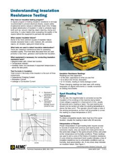
4 Soils made up of ashes, shale or loam tend to have the lowest soil Resistivity . Soils made up of gravel, sand or stone have the highest soil Resistivity . Figure 1 Technical Assistance (800) 343-1391 3 Moisture content, temperature and salts also affect soil Resistivity . Soil that contains 10% moisture by weight will as much as five times lower soil Resistivity than that which contains Soil at room temperature will be as much as four times lower in Resistivity than that at 32 degrees. So the time of year that you conduct the test can play a major role in the results. Finally salt content factors in the results in a big way. Just changing the composition by 1% can reduce soil Resistivity by as much as a factor of 20.
5 Therefore a quick visual analysis of the job site can give you a good idea as to whether you can expect low resistance from the installed grounding electrode system made up of a single ground rod or if you will need to install several rods to achieve the needed results. These conditions should be written down and kept with the test results. Temperature, moisture and soil type are easily identified. Salt content may be more difficult to determine. Now we are ready to take some measurements. As most commercially available ground rods are 8 to 10 feet long, it makes sense to check the expected soil Resistivity at a depth of 10 feet. Checking it 20 feet is also a good idea for comparison.
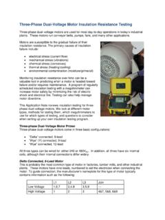
6 Using the Wenner method you need to space the four electrodes out an equal distance from each other in a straight line and spacing equal to the depth to be tested. See Figure 1. If we are Testing at a 10 foot depth then the four electrodes need to be spaced in a straight line 10 feet apart. If we are Testing at a 20 foot depth then the electrodes need to be spaced 20 feet apart and so on. To get a good indication of soil Resistivity of the grounding electrode site we should take five measurements and average them for the final answer. We should take them in a square pattern and then one on an inside diagonal of the square. See Figure 2. Now to use the simplified formula described earlier we need to observe one rule.
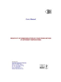
7 That is the depth of the test electrodes should be no more than 1/20th the spacing of the rods. For Testing at a ten foot depth the electrodes should be placed no more than 6 inches in the ground. No need to drive deeper for longer rods are spaced 10 feet apart and only six inches in the ground. The instrument is ready to be connected to the rode. We must connect the terminals of the instrument in sequence to the rod using the spools of wire provided. See Figure 3. Once the connections are made we can run the test. Turn the instrument on, place the selector switch in the soil Resistivity test position and press the test button. Observe and write down the resistance reading measured.
8 Do the same for each of the 5 measurements. For our test example let s assume that our average for the 5 measurements was ohms. Now apply the formula: = 2 AR= 2( ), (305cm) ( ) = 6515 ohm-cm Notice we converted 10 feet to 305 centimeters to simplify our math. (10 x ) = 305 Figure 2 Figure 3To convert feet to centimeters, multiply feet X X = ____cm10 X = X = X = X = Technical Assistance (800) DiameterInchesRod LengthFeetGround RodResistance OhmsSoil Resistivity (RHO)Ohm-centimetersGrounding NomographLet s look at the process of calculating the depth needed for a new ground rod installation.
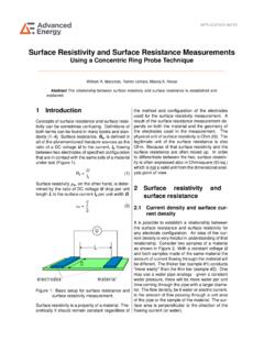
9 For this we will use a calculating tool called a nomograph. To begin with we need to make a few decisions. First what is the desired grounding electrode resistance needed? Second what is the diameter of the ground rods we will be using? With these two answers plus the measured soil Resistivity we can use the nomograph to calculate the depth required to achieve our objective. Let s say we need a resistance from this grounding system to be no more than 10 ohms and that we chose ground rods that have a 5/8 inch at our nomograph (page 4), we have five scales to work with: the R scale represents the desired resistance needed, for our work (10 ohms). The P scale represents soil Resistivity .
10 Our average value is 6515 ohm-centimeters obtained using a 4 pole ground resistance tester employing the Wenner test method. The D scale represents depth and is what we will use to find our answer. The K scale contains constants that will assist us in finding the depth. Lastly the DIA represents the diameter of the rods used. We will complete several simple steps to get our depth answer. Using the nomograph we first put a dot at 10 ohms on the R scale as it is our desires resistance. Next we put a dot at 6515 on the P scale representing our soil Resistivity measurement . We will have to do our best to approximate the location of this point between the 5000 and 10000 hash marks. Next we take a straightedge and draw a line between the dots we placed on the R and P scales and let the line intersect with the K scale and place a dot on the intersecting point.