Transcription of TELECOMMUNICATIONS - NASA
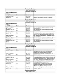
1 TELECOMMUNICATIONS PULSE-COOE MODULATION TELEMETRY UNIFIED S-BAND NAL CONDITIONER TRIPLEXER VHF/AM 0 FREQUENCY SWITCH P DATA LINK S-BAND POWER AMPLIFIER P-223 Location of main TELECOMMUNICATIONS equipment The TELECOMMUNICATIONS subsystem provides voice, television, telemetry, and tracking and ranging com munications between the spacecraft and earth, be tween the CM and LM, and between the spacecraft and astronauts wearing the portable life support system. It also provides communications among the astronauts in the spacecraft and includes the central timing equipment for synchronization of other equipment and correlation of telemetry equipment. For convenience, the TELECOMMUNICATIONS sub system can be divided into four areas: intercom munications (voice), data, radio frequency equip ment, and antennas. Most of the components of the TELECOMMUNICATIONS subsystem are produced by the Collins Radio Co.
2 , Cedar Rapids, Iowa. INTERCOMMUNICATIONS The astronauts headsets are used for all voice com munications. Each headset has two independently operated earphones and two microphones with self contained pre-amplifiers. Each astronaut has an audio control panel on the main display console which enables him to control what comes into his headset and where he will send his voice. The head sets are connected to the audio panels by separate umbilical cables. These cables also contain wiring for the biomedical sensors in the constant-wear garment. The three headsets and audio control panels are connected to three identical audio center modules. 173 The audio center is the assimilation and distribution point for all spacecraft voice signals. The audio signals can be routed from the center to the appro priate transmitter or receiver, the launch control center (for pre-launch checkout), the recovery forces intercom, or voice tape recorders.
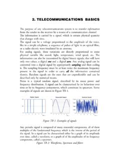
3 Two methods of voice transmission and reception are possible: the VHF/AM transmitter-receiver and the S-band transmitter and receiver. Transmission is controlled by either the push-to-talk switch located in the astronaut's umbilical cable or the voice operated relay circuitry during recovery operations. The push-to-talk switch also can be used like a tele graph key for emergency transmission. The VHF/AM equipment is used for voice com munications with the manned space flight network during launch, ascent, and near-earth phases of a mission. The S-band equipment is used during both near-earth and deep-space phases of a mission. When communications with earth are not possible, a VHF OMNI VOICE 2-GC OMNI OOWN VOICE UP-DATA BACKUP VOICE & EMERGENCY KEY TELEMETER (LOW BIT RATE) TELEMETER (HIGH BIT RATE) P 2-GC HIGH-GAIN UP-DATA, UP-VOICE DOWN VOICE, TELEMETRY TV NEAR EARTH & DEEP SPACE 2,600 N.
4 ML I 38,000 N. ML 22,000 N. ML WIDE BEAM DEEP SPACE BLIND AREA limited amount of audio signals can be stored on tape. During recovery, the VHF/AM and recovery intercom equipment are used to maintain contact with ground stations and with frogmen. DATA The spacecraft structure and subsystems contain sensors which gather data on their status and per formance. Biomedical, TV, and timing data also is gathered. These various forms of data are assimilated into the data system, processed, and then trans mitted to the ground. Some data from the opera tional systems, and some voice communications, may be stored for later transmission or for recovery after landing. Stored data can be transmitted to the ground simultaneously with voice or real-time data. Signals from some of the instrumentation sensors are fed into signal conditioning (converting) equip ment. These signals, and others which are already conditioned or don't need to be, are then sent to a MEDIUM BEAM 220,000 N _ M L 200,000 N.
5 ML NARROW BEAM LUNAR OPERATIONS: : VOICE, CM-LM RENDEZVOUS RADAR/ TRANSPONDER, CM-LM HIGH-GAIN ANTENNA OPERATIONAL (2500) P-224 174 .1 A 40 50 RANGE FROM EARTH'S SURFACE IN NAUTICAL MILES (TH OUSANDS) CSM communication ranges data distribution panel, which routes them to CM displays and to pulse-code modulation telemetry equipment. The latter combines them into a single signal and sends it to the premodulation processor. The premodulation processor is the assimilation, integration, and distribution center for nearly all forms of spacecraft data. It accepts signals from telemetry, data storage, TV, central timing, and audio center equipment. It modulates, mixes, and switches these signals to the appropriate trans mitter or to data storage. Voice and data command signals from the ground received over the S-band receiver also are supplied to the processor, which routes them to the audio center equipment or the up-data link (ground com mand) system.
6 Up-data is of three types: guidance and navigation data for updating the CM computer, timing data for updating the central timing equip ment, and real-time commands. The commands give the ground limited control over certain space craft TELECOMMUNICATIONS functions. RADIO FREQUENCY EQUIPMENT The radio frequency equipment is the means by which voice information, telemetry data, and ranging and tracking information are transmitted and received. The equipment consists of two VHF I AM transceivers (transmitter-receiver) in one unit, the unified S-band equipment (primary and sec ondary transponders and an FM transmitter), pri mary and secondary S-band power amplifiers (in one unit), a VHF beacon, an X-band transponder (for rendezvous radar), and the premodulation processor. The equipment provides for voice transfer be tween the CM and the ground, between the CM and LM, between the CM and extravehicular astronauts, and between the CM and recovery forces.
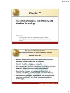
7 Telemetry can be transferred between the CM and the ground, from the LM to the CM and then to the ground, and from extravehicular astro nauts to the CM and then to the ground. Ranging information consists of pseudo-r andom noise and double-doppler ranging signals from the ground to the CM and back to the ground and X-band radar signals from the LM to the CM and back to the LM. The VHF beacon equipment emits a 2-second signal every 5 seconds for I ine-of-sight direction finding to aid recovery forces in locating the CM after landing. ANTENNAS There are nine antennas on the command and service modules, not counting the rendezvous radar antenna which is an integral part of the rendezvous radar transponder. These antennas can be divided into four groups: VHF, S-band, recovery, and beacon. The two VHF antennas (called scimitars because of their shape) are omni-directional and are mounted 180 degrees apart on the service module.
8 There are five S-band antennas, one mounted at the bottom of the service module and four located 90 degrees apart around the command module. The high-gain antenna is stowed within the SLA until the transposition and docking maneuver, when it is deployed so that it is at right angles to the module. It can be steered through a gimbal system and is the principal antenna for deep-space communications. The four S-band antennas on the command module are mounted flush with the surface of the module and are used for S-band communications during near-earth phases of mission, as well as for a backup in deep space. The two VHF recovery antennas are located in the forward compartment of the command module, and are deployed automatically shortly after the main parachutes. One of these antennas also is con nected to the VHF recovery beacon. EQUIPMENT All communication and data system units are in the command module lower equipment bay, mounted to coldplates for cooling.
9 LWO SCIMITAR VHF OMNIDIRECTIONAL ANTENNAS (180 DEGREES APART) FOUR S BANO OMNIDIRECTIONAL SLA 0 P-225 ANTENNAS RENDEZVOUS RADAR TRANSPONDER ANTENNA --., -lWO VHF BLADE -RECOVERY ANTENNAS STEERABLE S-BANO HIGH-GAIN ANTENNA Location of antennas 175 Audio Center (Collins Radio Co., Cedar Rapids, Iowa) -Center weighs pounds and is 4. 7 by by inches. It is a 28-volt, 20-watt gasket-sealed box with three identical headset amplifiers, one for each crewman. It provides communication among astronauts, between astro nauts and launch pad personnel, and post-landing recovery frogmen, recording of audio signals in conjunction with tape recording equipment, and relaying of audio signals. Central Timing Equipment (General Time Corp.) -This 10-pound unit provides time correlation of all spacecraft time-sensitive functions. It also generates and stores the real-time day, hour, minute, and second mission elapsed time in binary-coded decimal format for onboard recording and transmission to the Manned Space Flight Network.
10 It is normally synchronized to a con tinuously generated signal from the guidance and navigation computer. If the signal is lost, backup is provided by synchronizing to a self-contained source. The unit contains two power supplies for redundancy. Each is supplied from a different power source and through separate circuit breakers. The two power supplies provide parallel 6-volt de outputs, either one of which is sufficient to power the entire unit. Data Storage Equipment (Leach Corp., Azusa, Calif.) -This 40-pound unit is 22 by by 6 in ches and operates from 115-volt, 3-phase, 400-Hertz and 28-volt de power. Tape is one-inch, 14-track Mylar. It operates at three speeds: 3. 75, 15, and 120 inches per second. While being played back, the tape speed is selected automatically to Provide an apparent KBPS PCM data. It plays in a single direction, but a rewind mode is provid ed.