Transcription of Temperature Calibration - Fluke Corporation
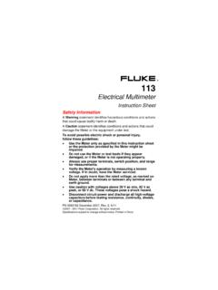
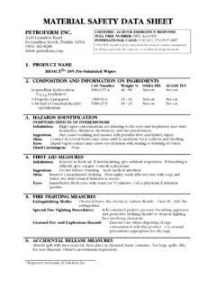
1 ZEROSPAN4 to 20 mA4 Wire RTD TransmitterRTD Sensor2200 C050100150200250300-200-1000100200300400 Ohms Vs. Temp (PT100)Technical DataTemperature CalibrationFluke 724 Temperature CalibratorFunctionFluke Temperature Test ToolsFluke 712 Fluke 714 Fluke 724 Fluke 725 Fluke 741 Fluke 743 Fluke 744 Fluke 55 XXFluke 50 SeriesTemperature plays a key role inmany industrial and commercialprocesses. Examples includemonitoring cooking temperaturein food processing, measuringthe Temperature of molten steelin a mill, verifying the tempera-ture in a cold storage warehouseor refrigeration system, or regu-lating temperatures in the dryingrooms of a paper Temperature transmitter willuse a measuring device to sensethe Temperature , and then regu-late a 4-20 mA feed-back loop to a controlelement that affectsthe Temperature ( ). The control ele-ment might consist ofa valve that opens orcloses to allow moresteam into a heatingprocess or more fuelto a burner.
2 The two most com-mon types of Temperature sens-ing devices are the thermocouple(TC) and resistive temperaturedetector (RTD). Fluke provides a broad rangeof Temperature Calibration toolsto help you quickly and reliablycalibrate your Temperature in-strumentation. A summary of thetemperature Calibration capabili-ties of Fluke Process Tools isshown Temperature from an RTD probe Measure Temperature from a T/C probe Simulate an RTD output Simulate an RTD into pulsed excitation current Simulate a T/C output Simultaneous output a T/C, measure mA Simultaneous output an RTD, measure mA Log a Temperature measurement Ramp a Temperature signal Loop power supply Multifunction Source and Measure Automatically calibrate Temperature switches Electronic data capture Upload documented data to PC Integrated HART communication 2 Fluke Corporation Temperature CalibrationTypical Temperature Calibration ApplicationsHow to calibrate a Thermocouple input transmitterThe Fluke 724 TemperatureCalibrator can provide the threethings necessary to calibrate atemperature transmitter.
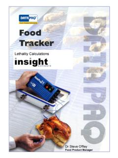
3 You cansource a Temperature , provideloop power, and measure theresulting output current. Thefollowing example shows how tocalibrate a Type K TC transmitterthat is ranged from 0-150degrees centigrade, generatingan output current range from4-20 Calibrator Setup1. Connect the 724 test leads tothe TC transmitter as output from the thermo-couple jacks on the 724 willsimulate a Temperature inputto the transmitter. The redand black test leads willprovide loop power to thetransmitter and will measurethe current resulting fromtemperature changes into Power on the 724 the mA button and theLOOP button to select mea-sure milliamps with 24V looppower Press the Meas/Source buttonuntil the lower portion of the724 display indicates thesource Depress the TC button until aTC type of K is Select the C button Set the Zero Point for thisapplication into the Calibra-tor. To do this set the displayinitially to C. You can usethe up and down arrow keysto change the output the left and right arrowsto control which decadevalue of the display is beingchanged.
4 When the displayreads , hold down the 0%key on the 724 and observethat 0% is displayed in thelower right corner of thescreen. This establishes theZero point for Set the Span Point in theCalibrator. Set the display tothe desired Span value forcalibration. In this examplethe display should read15 0 C. Depress the 100% keyand observe that 100% isdisplayed in the lower rightcorner of the screen. Thisestablishes the Span point an As Found Test8. Depress the 0% key; recordthe applied Temperature andthe corresponding Depress the 25% key (2)times; record the appliedtemperature and the corre-sponding mA the 100% key; recordthe applied Temperature andthe corresponding Calculate the errors for eachof the (3) points using thefollowing formula: ERROR =([(I-4)/16]-[(T/TSPAN])*100where Error is in % of span, Iis your recorded mA mea-surement, T is the recordedtemperature and TSPAN is thetemperature input span(100% - 0% points).)
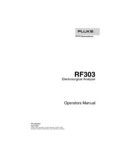
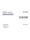
5 The errorcalculation table belowshows how to apply theformula to actual your calculated errors areless than the specifiedinstrument tolerance, thetransmitter has passed theAs-Found test. If the test hasnot passed, perform adjust-ments as the the 0% key to sourcethe proper Temperature for a4 mA output. Adjust the zeropotentiometer until thecurrent reading is the 100% key tosource the proper temperaturefor a 20 mA output. Adjust theSpan potentiometer until thecurrent reading is the 0% key againand adjust the zero potenti-ometer again if necessary, toget a mA an As Left TestRepeat steps 8 through 12 tocomplete the full calibrationprocedure on your MeasurementTC SourceT SpanFormulaError % C150 C([ )/16]-[0/150])* C150 C([ )/16]-[75/150])* C150 C([ )/16]-[150/150])* transmitter error calculation example100%25%25%RECALLMEASSOURCESTORESE TUPTCRTD0% Temperature CALIBRATOR724V F CVLOOPmAVmAMEASURESOURCE / MEASURE30V MAX ALL TERMINALS4W3 WVRTD TCCOMCOMLOOPTEST DC PWR++ Rosemount 444 Temperature Calibration Fluke Corporation 3 Measuring temperatureProcess temperatures can be verified using atemperature calibrator or digital this example, both the controller/indicatorand its input sensor can be verified at theprocess operating Temperature , documentedindicator verificationThe performance of a Temperature indicatorcan be verified by applying a calibratedsignal to the sensor input and noting theresults.
6 The performance of the indicator canbe documented using the 740 series calibra-tors by entering the indicator value using thekeypad. Please see the Custom Units/UserEntered Values application note, listed onpage 7, for more information and thermostat or temperaturecontrollersThe performance of a thermostat or tempera-ture controller can be determined by measur-ing the outputs while applying a temperaturesignal to the input. In this example, a Fluke740 series calibrator simultaneously variesthe input signal while monitoring contactclosure on the output. The calibrator thendocuments the measured setpoint, reset pointand deadband size. See the Limit Switchapplication note, listed on page 7, for moreinformation on switch a HART Temperature TransmitterHART smart transmitters require digitaladjustment if found to be out of task requires a precision calibrator and adigital configuration tool. The Fluke 744shown is connected to a Rosemount 3144 HART Temperature transmitter.
7 In this configu-ration, the 744 applies a T/C simulationsignal and measures the mA output anddigital PV. If adjustment is necessary, sensortrim, output trim and re-ranging can beperformed with the Fluke 744. See the HART application note, listed on page ( ZERO)VRTDmAmARTDV743 BDOCUMENTING PROCESS CALIBRATORENTERRANGESOURCE300 VMAX30 VMAX30 VMAX30 VMAXMEASCAT TCMeasuredControlledProcessFuel SupplyOutput orAlarmIndicatorSetpoint ( ZERO)VRTDmAmARTDV743 BDOCUMENTING PROCESS CALIBRATORENTERRANGESOURCE300 VMAX30 VMAX30 VMAX30 VMAXMEASCAT TCMeasuredControlledProcessFuel SupplyOutput orAlarmControlTCInputIndicatorSetpoint ControllerDisconnectedT/CControlValveAB C/ FTCTYPEINPUTOUTPUTTC30 VMAX714 THERMOCOUPLECALIBRATORM easuredControlledProcessFuel SupplyControlValveControlOutputSetpoint ControllerT/CInputTC ProbeTCmAmAVVRTDRTDSOURCE300 VMAX30 VMAX30 VMAX30 VMAXMEASCAT ( ZERO)DOCUMENTING PROCESS CALIBRATOR744+ 12345T+ HART ConnectionRedBlack3144 TransmitterTC+TC 4 Fluke Corporation Temperature CalibrationFluke 725 Multifunction Process Calibrator All the Temperature capabilities of Fluke 724below, plus.
8 Measure pressure with Fluke 700 PxxPressure Modules Source or measure frequency to 10 kHz Remote interface for automated benchtopapplicationsFluke 741, 743 and 744 DocumentingProcess Calibrators Measure or simulate JKTERSBLUNC thermocouples Measure or simulate 7 RTD types, per 712below, plus Cu 10 (47) Source or measure volts, ohms, mA, frequency Measure pressure with Fluke 700 PxxPressure Modules Electronically capture results of automatedprocedures Serial communication to PC (743, 744) HART communication (744) Fluke 724 TemperatureCalibrator Measure or simulate JKTERSBLUN thermocouples Measure or simulate 7 RTDtypes (see 712) Measure or source VDC, Measure 24 mA, with orwithout 24 volt loop supply Source TC or RTD whilemeasuring V or mA Handles pulsed RTD transmit-ters with pulses >5 msFluke 712 RTD Calibrator Measure or simulatePt 100 200 500 1000 (385),Pt 100 (3926), Pt 100 (3916)and Ni 120 (672) Measure or source 15 to3200 Handles pulsed RTD transmit-ters with pulses >100 ms Selectable F or C Banana jacks for 2W, 3W or4W measurementsFluke 714 ThermocoupleCalibrator Measure or simulate JKTERSBLU thermocouples Measure or source -10 to 75 mV Selectable F or C Thermocouple mini-jackterminationTemperature Calibration Fluke Corporation 5 Fluke 51 Series II and 52 Series II Large backlit dual display shows any combina-tion of T1, T2 (52 only), T1-T2 (52 only), plusMIN, MAX, or AVG Relative time clock on MIN, MAX, and AVG pro-vides a time reference for major events.
9 Electronic Offset function allows compensationof thermocouple errors to maximizeoverall accuracy Measures J, K, T, and E-types ofthermocouples Readout in C, F, or Kelvin (K). Fluke 51 Single InputDigital ThermometerFluke 52 Dual InputDigital ThermometerFluke 53 Single Input DigitalThermometer with data loggingFluke 54 Dual Input DigitalThermometer with data loggingThe Fluke 53 Series II and 54 Series IIInclude all the features listed for the 51and 52 Series II plus: Data Logging up to 500 points of data with useradjustable recording interval Additional thermocouple types R, S, and N (for atotal of 7 different types) Real time clock captures the exact time of daywhen events occur Recall function allows logged data to beeasily reviewed on the meter display IR communication port allows data to be ex-ported to optional FlukeView Temperature PCsoftware for further analysis and graphing65 Infrared Thermometer Range -40 to 500 C (-40 to932 F) resolution up to 200 Measurements in less than1 second Bright laser beam for easytargeting 8.
10 1 Optical Resolution MIN/MAX reading capture Large backlit dual display2620T/2635T RecordingThermometers 20 channel precision ther-mometer with SPRT ReferenceProbe Up to 18 channels TC Calibra-tion System Up to 9 channels RTD Calibra-tion System NIST/DKD certified calibrationto .05 C5500/5520 MultiproductCalibrator Verify TC and RTD probes Calibrate most handheldmultimeters and temperaturecalibrators Calibrate most functions ofFluke Process Calibrators Laboratory accuracy6 Fluke Corporation Temperature CalibrationTemperature Test Tool Summary Performance: Selected examplesFunctionRangeResolutionAccuracyN otes RT DMeasure -200 to 800 C8 RTD typesPT100-385 Simulate -200 to 800 C RT DMeasure -200 to 800 C7 RTD typesPT100-385 Simulate -200 to 800 C ResistanceMeasure 0-11,000 .01 .05% + 50 m 100 rangeSimulate 0-11,000 .01 .01% + 40 m ResistanceMeasure 15-3200 .1 .1 to 1 100 rangeSimulate 15-3200.