Transcription of Temposonics - ATI Systems
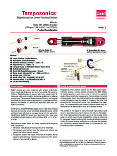
1 Temposonics Absolute, Non-Contact Position SensorsG-SeriesAnalog RedundantTemposonics GT2 and GT3 Measuring length 50 - 1500 mmMagnetostriction The absolute Temposonics linearposition sensors are based on theMTS developed magnetostrictivemeasurement principle. That combi-nes various magneto-mechanicaleffects and uses the physical hightprecise speed-measurement of anultrasonic wave (torsion pulse in itssensor element) for position detec-ting. sensor integrated signal proces-sing transforms the measurementsdirectly into market standard contactless principle - an exter-nal movable magnet marks the posi-tion - eliminates the wear, noise anderroneous signal problems and gua-rantees the best durability withoutany factorThe extremely robust sensor , ideal forcontinuous operation under harshestindustrial conditions is completelymodular in mechanic and electronicdesign.
2 A profile or rod-shaped sensor hou-sing protects the sensing element inwhich gives rise to the measurementsignal. The sensor head accommodates thecomplete modular electronic interfacewith active signal encapsulation ensures highoperating safety and optimum EMCprotection. The position transmitter, a perma-nent magnet - fixed at the mobilemachine part - drives contactlesslyover the sensor 's stroke and startsmeasuring through the housing wall. Up to 3 totally separated, independent measuring Systems in 1 housing Linear Absolute Measurement Contactless Sensing with Highest Durability Superior Accuracy: Linearity better 0,02 % Repeatability 0,001 % Direct Analog Output Compact design with a 10 mm measuring rod and standard mountingRedundancy for enhanced safetyI 2 ITemposonics-GT2+GT3 Analog MTS Sensors Temposonics G-Series RedundantThe G-Series Redundant sensor is designed for applications with high safety requirements.
3 Two or three measuring Systems , which work totally independent, are installed inside the compact sensor housing. Each measuring system contains its own canalwith sensor element, evaluation electronics, output signal, separated power supply, connector and sensor elements are integrated in one pressure proofed high-grade steel rod. Rod and fixing flange feature the approved standard dimensions with 10 mm dia-meter and M18x 1,5 winding. That qualifies the redundant sensor for measuring linear movements of control valves, linear drives, fluid cylinders and particular applications with safety relevant functions benefit from a redundant position measurement:- Valves and drives at power plants- Pitch settings at water- or wind turbines or at marine propellers- Ship control Systems and outputTemposonics G-Series with analog outputs provide direct analog outputs inclu-ding voltage and current, forward or reverse acting.
4 All outputs allow fulladjustment of Null and Span setpoints (minimum range 50 mm between setpo-ints) inside the active electrical strokelength. Since the outputs are direct, nosignal conditioning electronics are needed when interfacing with controllers ormeters. Active stroke length0 %100 %DisplacementV / mASensor field programmingTemposonics G-Series sensors are preconfigured at the factory by model codedesignation. If needed, MTS offers different external service tools for modifyingsensor parameters inside the active electrical stroke(minimum 50 mm bet-ween setpoints) via the standard connection cable. There is no need to open thesensors electronics. Following tools are available:1. Hand-Programmer G-Analogfor setups of measuring length inside the ordered output by pushing PC-Programmer G-AnalogThis hardware converter is required to communicate via serial port of WindowPC to the sensor .
5 Customized settings are possible by using a MTS program-ming software (CD-ROM) for:Analog:1. Null and Span; 2. Forward and reverse acting; 3. Output: Voltage/Current and output valuesI 3 ITemposonics-GT2+GT3 AnalogMTS Sensors Technical DataInputMeasured variablesPositionMeasuring range50 - 1500 mmOutputSensor model GT2 Two output channelsSensor model GT3 Three output / / +10 / + VDC (min. load controller: > 5 kOhms)Current4(0)..20 mA / (0) mA (min/max. load: 0/500 Ohms)Null/Span adjustment100 % of electrical stroke (Min. range 50 mm)AccuracyPosition measurement:- ResolutionAnalog: Infinite- Linearity< 0,02 % (Minimum 50 m)- Repeatability< 0,001 % (Minimum 2,5 m)- Hysteresis< 4 m - Update time (ms)Analog: < 1 ms typical- Ripple< 0,01 % conditionsMagnet speedanyOperating temperature electronic housing-40 C.
6 +75 CDew point, humidity90% rel. humidity, no condensationProtectionIP 67 Shock test100 g single hit, IEC-Standard 68-2-27 Vibration test15g / 10 - 2000 Hz, IEC-Standard 68-2-6 Standards, EMC testElectromagnetic emission EN 50081-1 Electromagnetic immunity EN 50082-2EN 61000-4-2/3/4/6, Level 3/4, Criterium A, CE-qualifiedForm factor, materialSensor headAluminumRod with flangeStainless steel / AISI 304-Pressure rating350 bar, 700 bar peakPosition magnetRing magnets, U-magnets InstallationMounting positionany orientationRodThreaded flange M18 x 1,5, nut M18 Position magnetMounting plate and screws from antimagnetical material Electrical connectionConnection type6 pin connector M16 or integral PUR-cable with open endsInput voltage24 VDC (-15 / +20 %)
7 - Polarity protectionup to -30 VDC- Overvoltage protectionup to 36 VDCC urrent drain100 mA typicalRipple< 1 % S-SElectric strength500 VDC (DC ground to machine ground) Temposonics -GT2+GT3 Analog MTS Sensors I 4 IConnector outlet D60 Cable outlet H0212,5800,55136 Active stroke63,5800,53651 Active stroke63,527M18x1,5 InactiveM18x1,5 InactiveHEX 70 mm 13,5 4,2 oncircle 24 Height: 8 mm 33 Ring magnet OD33 Part No. 201 542-2 Composite PA-Ferrite-GF20 Weigth ca. 14gOperating temperature:-40 .. +100 CSurface pressure max. 40 N/mm2 Fastening Torque for M4 screws max. 1 Nm 33 13,560 circle 24 Height: 8 mm 4,2 onPart No. 251 416-2 Composite PA-Ferrite-GF20 Weigth ca. 11gOperating temperature:-40 .. +100 CSurface pressure max. 40 N/mm2 Fastening Torquefor M4 screws max.
8 1 NmU-magnet M OD33 Height: 8 mm 13,5 25,4 Ring magnet OD25,4 Part No. 400 533 Composite: PA-FerriteWeigth ca. 10gOperating temperature:-40 .. +100 CSurface pressure max. 40 N/mm2 High Pressure Rod DesignTemposonics-GTwith a pressure-resistant stainless steel flange andsensing rod is suitable for use inhydraulic cylinders and externally inall applications where space is a pro-blem. Position measurement is viaring or U-magnets travelling alongthe sensing rod without any mechani-cal contact. Selection of position magnet(not on delivery)Connection types 1. Connector outlet D606 pin Male receptacle M16 2. Cable outlet H022 m PUR cable 3 x 2 x 0,25 mm2 Cable 6,8 mmScreened unshielded twisted pair50 mm bending radius at fixed installationTemposonics-GT2+GT3 AnalogMTS Sensors I 5 IFlexible installation in any position543621 Pin 1 2 3 4 5 6 CablegreypinkyellowgreenbrownwhiteConnec torAnalogV/mADC GroundPC-ProgrammingPC-Programming+ 24 VDC (-15 / +20 %)DC GroundMale insert connectorrear of cable connectorRod modelMount the sensor via flange thread or a hex nut.
9 If possible, non-magnetizablematerial should be used for mounting support (dimensions as shown). Withhorizontal mounting, longer sensors (from 1 meter) must be provided withmechanical support. Hydraulic sealingRecommended is sealing of the flange facing with O-Ring ( 22,4 x 2,65) ina cylinder cover nut or an O-Ring 15,3 x 2,2 in installationWhen used for directstroke measurement in fluid cylinders, the sensor 's highpressure, stainless steel rod installs into a bore in the piston head/rod assem-bly as illustrated. That guarantees a longlife and trouble-free operation - inde-pendent of used hydraulic connector(recommended, not on delivery) 19,5 Housing: Zinc nickel platedTermination: SolderContact insert: Silver platedCable clamp: PG7 Max. Cable- 6mmCable clamp: PG9, M16 Max.
10 Cable- 8 mm3854 18546 pin female connector M16, PG9 Part No. ST C0 9131 D06 PG96 pin 90 female connector M16insert adjustable in 45 positionsPart No. ST C0 9131-6 Minimum assembly > 30> 15 Hex 70 Torque:< 50 NmRecommendedhydraulic sealing1. Non-magnetizable material2. Magnetizable materialAntimagneticspacerAlternativesea lingO-Ring 15,3 x 2,2 When mounting the sensor a basic tool with max. 8 mm dimension has to beused. Thereby attention must be paid, that the tool is placed at the flange exclu-sively. Using the twice redundant version GT2 a protective cap covers the third outlet D60SW 70< 8 mm< 50 NmTemposonics-GT2+GT3 Analog MTS Sensors I 6 ITemposonicsSensor modelGT2= Dual redundant GT3= Triple redundantForm factorM= Flange M18 x 1,5 (Standard)Measuring length 0050.