Transcription of THE COMPONENTS OF TOTAL HEAD - …
1 THE COMPONENTS OF TOTAL HEAD This chapter will introduce some of the terminology used in pumping systems. The COMPONENTS of TOTAL Head will be examined one by one. Some of the more difficult to determine COMPONENTS , such as equipment and friction head, will be examined in more detail. I hope this will help get our heads together. THE COMPONENTS OF TOTAL HEAD TOTAL Head is the measure of a pump's ability to push fluids through a system. TOTAL Head is proportional to the difference in pressure at the discharge vs. the suction of the pump. It is more useful to use the difference in pressure vs. the discharge pressure as a principal characteristic since this makes it independent of the pressure level at the pump suction and therefore independent of a particular system configuration. For this reason, the TOTAL Head is used as the Y-axis coordinate on all pump performance curves (see Figure 4-3). The system equation for a typical single inlet single outlet system (see equation [2-12]) is: )()(21122221211212 HzHzvvgHHHEQFP+ ++ + + = [3-1] TSvEQFPHHHHH + + + = [3-1a] SSDSvEQFPHHHHHH + + + + = [3-1b] Equations [3-1a] and [3-1b] represent different ways of writing equation [3-1], using terms that are common in the pump industry.
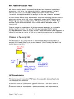
2 This chapter will explain each one of these terms in details. TOTAL STATIC HEAD ( HTS) The TOTAL static head is the difference between the discharge static head and the suction static head, or the difference in elevation at the outlet including the pressure head at the outlet, and the elevation at the inlet including the pressure head at the inlet, as described in equation [3-2a]. HHHTSDSSS= [3-2] )(1212 HzHz+ += [3-2a] H2 and H1 are the pressure heads at points 2 and 1 respectively. Some people include these pressure heads with the elevation head, others do not. I will be using the former approach, but either way the pressure heads have to be considered. The discharge static head ( HDS) is normally positive (assuming H2 = 0 ), since fluid is usually pumped 3 2 THE COMPONENTS OF TOTAL HEAD to a higher elevation. However, it may on occasion be negative (for example, lower discharge pipe end than pump centerline) and the complete system must be evaluated before it is known if a pump is required or not.
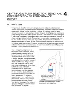
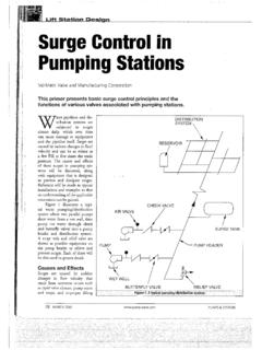
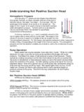
3 The suction static head ( HSS) can either be negative or positive, depending on whether the pump centerline is below the suction fluid surface or above, and the value of suction tank fluid surface pressure head (H1). suction STATIC HEAD ( HSS) The suction Static head is the sum of the elevation and pressure head at the inlet of the system, minus the elevation of the pump center line, as stated in equation [3-3]. The inlet of the system is located at point 1, which is the surface of the suction tank fluid. H1 is the pressure head at the suction tank fluid surface. If the tank is open to atmosphere then H1 = 0. Typical pumping configurations are shown in Figure 3-2, the pump suction is under positive pressure in A, and possibly under negative relative pressure in B. Figure 3-1 Relationship between the various heads in a pumping system. THE COMPONENTS OF TOTAL HEAD 3 3 The suction Static head in these two cases is: SzHzHSS += 11 [3-3] Figure 3-2B presents a situation where the pump has to lift the fluid up to the pump suction .
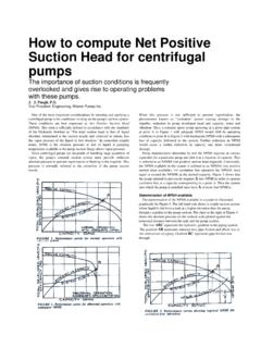
4 The head at the suction is described as suction lift. This head is normally negative with respect to atmospheric pressure since the term z1 zS is negative (assuming H1 = 0 or the same as the atmospheric pressure). NET POSITIVE suction HEAD AVAILABLE ( ) The Net Positive suction Head Available ( ) is the TOTAL energy per unit weight, or head, at the suction flange of the pump less the vapor pressure head of the fluid. This is the accepted definition which is published by the Hydraulic Institute s Standards books (see the HI web site at www. ). The Hydraulic Institute is the organization that formulates and promotes the use of common standards used throughout the pump industry in the United States. The term "Net" refers to the actual head at the pump suction flange, since some energy is lost in friction prior to the suction . Why do we need to calculate the This value is required to avoid cavitation of the fluid. Cavitation will be avoided if the head at the suction is higher than the vapor pressure head of the fluid.
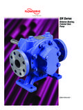
5 In addition, the pump manufacturers require a minimum to guarantee proper operation of the pump, they call this the , where R stands for required. Figure 3-2 suction static head and suction static lift. 3 4 THE COMPONENTS OF TOTAL HEAD To determine , first we calculate the pressure head HS at point S. A control volume is positioned (see Figure 3-3) to intersect the suction inlet of the pump and the fluid surface of the suction tank. The pressure head at any point on the suction side of the pump is given by equation [2-15] where the subscript X is replaced by S: )(2)()()(1221111 HzzgvvHHfluidofftHSSSEQSFS+ + + + = [3-4] Figure 3-3 Using the control volume for calculating the pressure head at point S. The specific energy or head E for any point in the system is the sum of the elevation (potential) energy, the velocity (kinetic) energy and the pressure energy. E is given by: zgvHE++=22 [3-5] By definition, the available at the pump suction (point S) is based on a reference plane located at the pump suction centerline (z = 0 ).
6 We can understand why since using any other reference will increase or decrease the energy level at point S which is obviously incorrect (see Figure 3-3). Therefore equation [3-5] becomes: gvHESSS22+= [3-6] THE COMPONENTS OF TOTAL HEAD 3 5 The head SE is given in equation [3-6], the barometric head (HB) is added to HS to convert SE from feet of fluid to feet of fluid absolute. Therefore equation [3-6] becomes: BSSHgvHabsolfluidofftES++=2).(2 [3-7] The value of HS in equation [3-4] is substituted in equation [3-7] to give: BSEQSFSHH zzgvHHabsolfluidofftES++ ++ + = )(2)().(121111 [3-8] BOILING LIQUIDS Different liquids boil at different temperatures for a fixed pressure; also, different liquids boil at different pressures at a fixed temperature. The temperature required to vaporize a liquid varies as the pressure in the surrounding environment. For example, water boils at a temperature of 212 0F at a surrounding pressure of psia (the air pressure at sea level).
7 However, a temperature of 189 0F is required to boil water at a pressure of 11 psia which is the atmospheric pressure at 8,500 feet of elevation above sea level (or the altitude of Mexico city). A short digression is in order. Since water boils at a lower temperature in, say, Mexico City than a city which is close to sea level, does this mean that it takes a longer time to boil an egg in Mexico city? Yes, it will take longer in Mexico City. Why? Because the same amount of heat transfer is required to get the egg to the right consistency regardless of the water temperature. It will take longer to transfer the amount of heat required to cook the egg if the water is boiling at a lower temperature. For most of us water boils at the high temperature of 212 0F (100 0C), it is very surprising to find that it takes 4 minutes to boil a 3-minute egg in Mexico City. The pressure at which a liquid boils is called the vapor pressure and is always associated with a specific temperature.
8 When pressure decreases in the fluid's environment, the boiling temperature drops. Many liquids ( acetone, methyl alcohol, benzene, etc.) have a lower vapor pressure than water at the same temperature. Since the pressure throughout a system can vary drastically, it is important to consider the vapor pressure of the liquid in order to avoid vaporization. Data on vapor pressure vs. temperature for many liquids is readily available (see reference 1, 2 and 8). 3 6 THE COMPONENTS OF TOTAL HEAD VAPOR PRESSURE AND CAVITATION The pressure near the impeller eye is lower than the pressure at the pump suction flange, and depending on the kind of fluid and temperature, may be low enough for vaporization to occur. When this happens, both, vapor and liquid, will enter the pump, and the capacity of the pump will be reduced. The point of lowest pressure is near the eye of the impeller on the underside of the vane (see Figure 3-6), where bubbles can form. Only small bubbles are formed because the fluid is rapidly compressed as it travels from the start of the impeller vane to its tip.
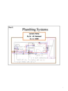
9 The rapid compression of bubbles causes small pieces of metal to be dislodged from the surface. These bubbles collapse rapidly in the high pressure near the tip of the vane causing noise and vibration. This rapid collapse of vapor bubbles is known as cavitation and is accompanied by a distinct gravely sound similar to the sound made by a cement mixer. The system should be designed in such a way as to provide sufficient available to avoid cavitation under normal running conditions. Figure 3-4 Vapor pressure vs. temperature. THE COMPONENTS OF TOTAL HEAD 3 7 In order for the liquid to stay in a fluid state and not vaporize, the head at the inlet of the pump must be above the vapor pressure head of the fluid: vaSHE where Hva is the vapor pressure head of the liquid. The Net Positive suction Head Available ( ) is the difference between the head (SE) at the pump suction and the vapor pressure head (Hva). vaSavailHEHSPN =.. [3-9] By substituting the value of SE from equation [3-8] into equation [3-9] then: vaBSEQSF availHHHzzgvHHabsolfluidofftHSPNS ++ ++ + = )(2)().
10 (.. [3-10] where HB and Hva are in feet of fluid. Vapor and barometric pressures are often given in pounds per square inch absolute (psia). The conversion to feet of fluid absolute is: HftoffluidSGppsia().()= 231 by substitution into equation [3-10]: ))()(( )(2)().(.. + ++ ++ + = [3-11] The in equation [3-10] and [3-11] is in feet of fluid absolute and is a head term, which is independent of fluid density. Since the pump manufacturers use water as the fluid, the value they provide is in feet of water absolute. The pump requires a minimum suction pressure head in order to function properly and avoid cavitation. This is known as the required, which the pump manufacturer gives for a specific pump model, impeller diameter, speed and flow rate. In order to satisfy the pump manufacturer's requirements: ..reqavailHSPNHSPN 3 8 THE COMPONENTS OF TOTAL HEAD Figure 3-5 shows typical relative proportions of the terms in equation [3-10].)