Transcription of The Design of Electron and Ion Guns, Beams, and Collectors
1 Proc. EBIS Symposium, Tokyo, 2004- The Design of Electron and Ion guns , Beams, and Collectors Reinard Becker1 and William B. Herrmannsfeldt2 1 Institut f r Angewandte Physik der Universit t Frankfurt/M, Fach 180, D-60054 Germany 2 SLAC, Stanford University, CA, USA ABSTRACT. The well known SLAC Electron Trajectory Program (EGUN) has been ported to PCs and has been developed into a family of programs for the Design and the optimization of particle optics devices including Electron and ion guns , beam transport sections and Collectors . We will discuss the application of these tools for the Design and the optimization of the essential parts of EBIS/T devices.
2 The discussion will include conditions in which restrictions in the reliability of simulations may occur due to the mathematical modeling and how to overcome them. INTRODUCTION The Electron beam formation, its focusing properties and the expansion and spreading of the beam over the collector surface need reliable tools for the Design of magnetic shielding of solenoids as well as for the calculation of Electron trajectories under the influence of electric, magnetic and self fields. This knowledge, acquired over many decades for the Design of traveling wave tubes (TWTs), Klystrons, and gyrotrons has resulted in professional software, used in industry as well as in accelerator laboratories around the world.
3 The anchestor of the family of simulation tools is EGUN [1,2,3,4], a finite difference Poisson solver, combined with a relativistic ray tracing routine, taking into account the magnetic field of the beam itself and the space charge of the beam . Numerous options became incorporated with time and today there is hardly to find an application, which cannot be simulated with this 2D rectangular and axisymmetric simulation program. After porting of the program to PCs, giving the name EGN87c, adequate graphical software became necessary. Also the program POLYGON [5] made it much easier to set up boundaries for EGN.
4 For the calculation of static magnetic fields without saturation, the boundary element program INTMAG [6,7] has been developed. By its calculus, the numerical values are very smooth and allow for the meaningful generation of 6th order axial field derivatives, which in turn allowed to calculate the off-axis fields in EGN87c with in a convenient, fast, and accurate way. The latest Proc. EBIS Symposium, Tokyo, 2004- member of such simulation programs is IGUN [8,9], a true child of EGUN, but with an option to simulate the plasma sheath for the extraction of positive ions. For the convenience of users some analyzing and graphic file converters have been added.
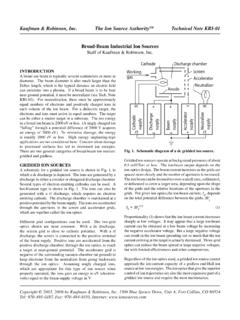
5 The latest and most advanced of them is CPLCOMP, which is a print and file conversion composer for the graphics output files. The possible combination of these programs is shown by Fig. 1 FIGURE 1. Schematic drawing of the connections between the programs of the EGUN/IGUN family, see also Design OF Electron guns The Design of an Electron gun usually starts with the definition of desired parameters, like current, energy, available focusing, life time of the cathode and other constraints. The suitable simulation tool is in any case EGN2W, how the new EGUN version for Windows is called today.
6 The input files for EGN2W are provided by POLYGON, which converts polygonal boundary input to the required form of mesh oriented input for EGN2W. POLYGON also reads and augments input parameter lists in NAMELIST format, includes magnetic field data and provides a valid input file for EGN2W. The geometrical part of polygonal boundary definition is most conveniently processed with GPED, a graphical interactive editor for POLYGON syntax, useful for POLYGON, INTMAG, and IGUN. As an example, we show the steps for simulating the MEDEBIS gun [10,11], which has high perveance ( A/V3/2) and high compression (110) under immersed flow conditions. Proc. EBIS Symposium, Tokyo, 2004- MEDEBISGun (non-thermal, mesh= mm, ,HOE) &INPUT1 RLIM=130,POTN=7,POT=0,3000,2000,0,3000,3 700,2000,MAGSEG=-1, PUNIT=1E-3,POIS=3 &END &INPUT3 BMULT=2,BZA= +01, +01, +01, +01.
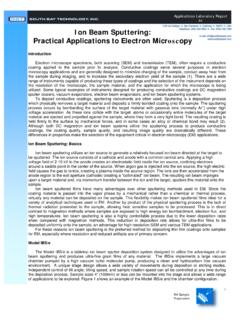
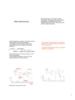
7 +03, +03, +03, +03, +03, &END 1, 0, 0 1, , 4, , 4, , 15 4, , 26 1004, , 26 2 4, 13, 28 2, 13, 31 2, , 31 2, , 2, , 2, 3, 2, 3, 1002, 4, 1 2, 10, 2, 11, 2, 13, 6, 13, 6, 4, 1006, 4, 1 6, 3, 60 0, 0, 60 1, 0, 0 &INPUT5 START ='SPHERE', RMAX = , RAD = +03, MAXRAY = -87, LSTRH = 1, UNIT = ,NS=15, AV=10, AVR=1, LM=1000 &END FIGURE 1. Input file for POLYGON of the MEDEBIS gun FIGURE 2. Result of EGN2W calculation for the MEDEBIS gun Proc. EBIS Symposium, Tokyo, 2004- The input file has 4 parts, which can be clearly distinguished in Fig. 1: 1) definition of the basic parameters (INPUT1) 2) axial values for the magnetic field (INPUT3 truncated) 3) input of boundary points in POLYGON syntax (presented here in 2 columns) 4) definition of runtime variables (INPUT5).
8 While the definitions of NAMELISTs INPUT1, INPUT3, and INPUT5 are prescribed by the EGN2W manual, we will explain to some detail here the POLYGON syntax, comparing Fig. 1. and Fig. 2: A mesh independent boundary point is described by 3 numbers: an integer for the potential number and 2 floating point numbers for the values of the r and z coordinate. The first point is the cathode electrode (number 1) at r=0, z=0. The second point shows the end of the spherical cathode shape at r= , z= POLYGON has a special interpretation for the cathode electrode: if only 2 points will be given, a spherical (in axisymmetric coordinates) or as cylindrical (in rectangular coordinates) shape will be assumed.
9 Then input continues with the focusing electrode with potential number 4. No gap is assumed between the egde of the cathode and the begin of this electrode, therefore the same coordinate values as for the end of the cathode are used as a start for this electrode. Then we have these numbers: 4, , 26 1004, , 26 2 4, 13, 28 2, 13, 31 Adding 1000 to the potential number is a signal to POLYGON to insert a circle of radius 2 and center r= , z=26 between points with r= , z=26 and r=13, z=28. Then we see the electrode number changing from 4 to 2 at r=13, z=31. POLYGON will insert Neumann boundary points here automatically.
10 Finally the first point is reached again, which is a signal to POLYGON that the boundary is closed and input complete. POLYGON syntax has several features to ease the input of complicated boundary shapes, however, even simpler is the input and the modification of existing input files by GPED, which is a dedicated CAD system with interactive graphics for POLYGON syntax files. As a result of running POLYGON with the above input file, an input file for EGN2W is obtained, which produces the plot of trajectories and equipotential lines as shown in Fig. 2. Clearly, this is an immersed field gun with a rippling beam after compression in the increasing magnetic field.