Transcription of The Flame Ionization Detector - UMass Amherst
1 51422 The Flame Ionization DetectorGeneral InformationFID pneumaticsSpecial considerationsConditions that prevent the Detector from operatingDetector shutdownJetsAutomatic reignition Lit offsetProcedure: Changing the auto-reig-nite setpointElectrometerData ratesProcedure: Using fast peaksOperating the FIDC olumns and TrapsGas pressuresOperating with EPCP rocedure: Using the FIDC heckout Conditions andChromatogramFID checkout conditionsTypical FID checkout chromatogramMaintaining a Flame IonizationDetectorCorrecting FID hardware problemsReplacing or cleaning the jetProcedure: Removing and inspect-ing the jetProcedure: Cleaning the jetProcedure: Installing the jetCleaning the collectorProcedure: Removing the collectorProcedure: Cleaning the collectorProcedure: Reassembling thedetectorProcedure.
2 Replacing the FID ignition wireThe Nickel Catalyst TubeGas flowsTemperatureRepacking the catalyst515515 The Flame Ionization DetectorGeneral InformationThe Flame Ionization Detector passes sample and carrier gas from the column through a hydrogen-air Flame . The hydrogen-air Flame alone creates few ions, but when an organic compound is burned there is an increase in ions produced. A polarizing voltage attracts these ions to a collector located near the Flame . The current produced is proportional to the amount of sample being burned. This current is sensed by an electrometer, converted to digital form.
3 And sent to an output pneumaticsFigure 73 illustrates the pneumatics design for the 73 Schematic of a Flame Ionization detectorFilterfritsProportionalvalvesPre ssure sensors RestrictorsAir inH2 inMakeup inVentPSPSPSP ressurecontrol loops516516 General InformationThe Flame Ionization DetectorSpecial considerationsSpecial considerationsConditions that prevent the Detector from operating Temperature set below 150 C Air or hydrogen flow set at Off or set at Ignition failureDetector shutdownIf a critical Detector gas is shut down due to a pneumatics or ignition failure, your Detector shuts down.
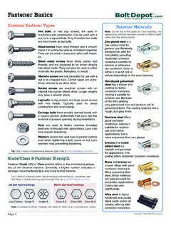
4 This turns off everything except the Detector temperature and makeup gas InformationThe Flame Ionization DetectorJetsJetsThere are two types of FID available. The capillary optimized FID is only used with capillary columns, and the adaptable FID fits packed columns and can be adapted to fit capillary 59 Jets for the Capillary-Optimized FIDT able 60 Jets for the Adaptable FIDYour Detector is shipped with a capillary column jet. If you are doing simulated distillation or high-temperature runs, you must change the jet. Instructions appear in Replacing or cleaning the jet.
5 Jet type Part tip mm ( )High-temperature(use with simulated distillation) mm ( )Jet typePart tip mm ( )Packed mm ( )Packed wide-bore (use with high-bleed applications) (use with simulated distillation) mm ( )Capillary optimized fittingAdaptable fitting518518 General InformationThe Flame Ionization DetectorAutomatic reignition Lit offsetAutomatic reignition Lit offsetLit offset is the expected difference between the FID output with the Flame lit and the output with the Flame off. If the output falls below this value, the FID will attempt to reignite twice. If the output does not increase by at least this value, the Detector shuts down all functions except temperature and makeup gas default setting for Lit offset is picoamps.
6 This is a good working value for all but very clean gases and systems. You may want to change this setpoint if: Your Detector is attempting to reignite when the Flame is still on, thus producing a shutdown. Your Detector is not trying to reignite when the Flame is : Changing the auto-reignite setpointLit offset1. [Press [Config][Front Det] or [Config][Back Det].2. Scroll to Lit offset and enter a default is 0 to disable the automatic reignite setpoint range is 0 to InformationThe Flame Ionization DetectorElectrometerElectrometerThe Configure Detector control table contains an On/Off setpoint for the Electrometer.]
7 You do not need to turn the electrometer on and off when operating your FID. The only time you need to turn off the electrometer is when cleaning the not turn off the electrometer during a run. It will cancel Detector ratesAnalog output for the FID can be presented at either of two speeds. The faster speed allows minimum peak widths of minutes, while the standard speed allows peak widths of : Using fast peaksIf you are using the fast peaks feature, your integrator must be fast enough to process the data coming from the GC. It is recommended that your integrator bandwidth be at least 15 Hz.
8 To use fast peaks:Digital output to the ChemStation is available at eleven speeds ranging Hz to 200 Hz, capable of handling peaks from to 2 minutes wide. Consult Signal Handling .The fast peaks feature does not apply to digital Press [Config][Signal 1] or [Config][Signal 2]2. Press [On]520 Operating the FIDThe Flame Ionization DetectorOperating the FIDUse the information in Table 61 when selecting temperatures and flows. Choose a minimum source pressure from Figure 61 Recommended Temperature and Flow Rates FIDGasFlow range(mL/min)Suggested flow(mL/min)Carrier gas(hydrogen, helium, nitrogen)Packed columnsCapillary columns10 to 601 to 5 Detector gasesHydrogenAir24 to 60*200 to 600*40 450 Column plus capillary makeupRecommended: nitrogenAlternate.
9 Helium10 to 6050 Detector temperature<150 C, Flame will not light, prevents condensation damageDetector temperature should be approximately 20 C greater than highest oven ramp temperature depending on the column offset [Config][Front Det] or [Config][Back Det]If the Detector output (when the Flame is on) minus the Detector output (when the Flame is off) falls below this value, the FID attempts to reignite twice. If output does not increase by at least this value, the Detector shuts pA is the recommended pA disables the autoreignite *The hydrogen-to-air ratio should be between 8% and 12% to keep the Flame the FIDThe Flame Ionization DetectorGas pressuresGas pressuresChoose a flow, find a pressure.
10 Set source pressure 10 psi (70 kPa) 74 Typical pressure/flow relationships for FID gases(at 25 C and 1 atmosphere of pressure)1020304050607001020304050607080 (psig) (mL/min)FLOW(mL/min)10203040506070(psig) the FIDThe Flame Ionization DetectorOperating with EPCO perating with EPC Figure 75 FID control tableTemperature, CHydrogen flow, mL/minAIr flow, mL/minTurn off for packed capillary columns, seemakeup gas flow mode gas typePress [On] to ignite flameDisplays output gas flow mode:If column dimensions are specified, the control table will also includeTo change makeup mode, scroll to Mode: and press [Mode/Type].