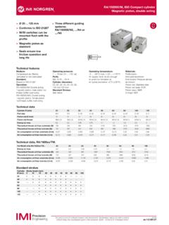
Transcription of The Norgren Guide to SpecifyingPneumaticActuators
1 The Norgren Guide toSpecifying Pneumatic ActuatorslDesign theorylApplicationslBore and stroke selectionCONTENTSI ntroduction5 Fundamental designs5 Single acting cylinders5 double acting cylinders6 magnetic cylinders6 Rodless cylinders6 Rotary actuators6 Clamping cylinders7 Bellows7 Cylinder sizing for thrust8 Useable thrust8 Clamping applications9 Dynamic applications9 Piston rod buckling9 Speed control9 Increasing speed12 Cycle times12 Cylinder air consumption13 Seals14 O ring piston seals14 Cup seals15 Z rings15 O ring barrel seals15 Cushion seals15 Piston rod seals15 Piston rod bellows15 Extreme operating temperatures16 Wear ring16 Cushion design16 Shock absorbers17 Standards18 Non standard dimensions18 Types of construction19 Sealed for life19 Micro cylinders19 Round line cylinders19 Small bore ISO19 Compact cylinders 12-40mm bore19 Serviceable20 Light and medium duty20 Compact cylinders 50-100mm bore20 ISO/VDMA profile20 ISO/VDMA (exposed tie rod)
2 20 Heavy Duty20 Mountings21 Rigid mountings21 Articulated mountings21 Installation22 Non rotational guiding22 Locking23 Rodless cylinders24 Rodless cylinder with brake24 Integrated valves24 Heavy duty rodless cylinder25 Cylinder variants25 Through rod 25 Multi position25 Tandem25 Duplex26 Custom piston rod end26 Extreme operating temperatures26 Special Purpose Actuators26 double stroke cylinders26 Positioners and servo cylinders27 Open loop applications27 Closed loop applications27In line positioners28 Servo cylinders29 Universal positioner29 Hollow piston rod cylinders30 Impact cylinders31 Principal of operation31 Installation32 Common terminology variants323 LIST OF ILLUSTRATIONSA djustable cushion cylinder6 Adjustable shock absorber42 Banjo flow regulators 25 Bellows14 Braking unit 72 Calculating equivalent mass43 Closed loop control84 Compact cylinder47 Compact guided cylinder62 Conventional flow regulators24 Cushion seal36 Cycle times28 Cylinder installation arrangements20 Detail of sealing strip section68 double acting clamp cylinder13 double acting non cushioned cylinder4 double rack and pinion11 double stroke (fixed carriage design)
3 81 Duplex cylinder79 Effective length, centrally mounted cylinder19 Effective length, rear mounted cylinder18 Energy graph94 Energy ratings92 External cushioned circuit 40 External guide70 Fixed cushion cylinder5 Fixed range positioner 85 Four pillar frame96 Full and restricted port aperture22 Heavy duty cylinder51 Heavy duty rodless cylinder75 Hollow rod cylinder91 Impact cylinder and valve93 Integrated valve73 Internal guide69 ISO Guide block63 ISO Guide block with locking units64 ISO RM/8000 series46 Locking unit66 Long stroke57M/29000 detail87M/30000 detail86 magnetic cylinder7 Main components of a cylinder1 Maximum stroke length21 Micro cylinder44 Mountings for ISO/VDMA cylinders53 Mountings for small bore ISO cylinders52 Non adjustable unit41 Non-rotating VDMA61 O Ring section32 Offset load bending moment59 Open loop 83 Out of alignment bearing58 Piston and rod diameters15 PRA/8000/M cylinder49 Pre-exhaust
4 Circuit29 Precision roller guide71 Proportional band graph90 Quick exhaust valve section27RA/8000/M cylinder50 Rack and pinion10 Rigid mounting styles54 Rod bellows38 Rod/wiper seal37 Rodless cylinder8 Rodless cylinder mountings74 Rotary vane9 Round line cylinders45 Section of a Z ring34 Section of a cup seal33 Section of barrel seal35 Section of Lintra67 Sequence of cushioning39 Serviceable compact48 Single acting clamp cylinder12 Single acting cylinder2 Single acting cylinder with no spring, push and pull3 Slide unit65 Speed graph26 Speed/pressure graph23 Swivel mounting styles55 Table of consumption30 Table of thrust and pulls, single acting cylinders16 Table of thrust and pulls, double acting cylinders17 Tandem cylinder78 Three stages of operation95 Three thread types80 Through rod76 Twin stroke principle82 Two cylinder multi position77 Types of seals31 Universal positioner88 Weight of cylinder60 Weight on the end of the rod56 Zero adjustment graph894 INTRODUCTIONP neumatic actuators, of which cylinders are the most common,are the devices providing power and movement to automatedsystems, machines and processes.
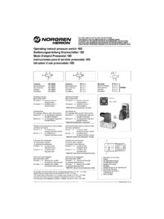
5 A pneumatic cylinder is asimple, low cost, easy to install device that is ideal forproducing powerful linear movement over a wide range ofvelocities, and can be stalled without causing internal conditions can be easily tolerated such as highhumidity, dry and dusty environments and repetitivecleandown with high pressure diameter or bore of a cylinder determines the maximumforce that it can exert and the stroke determines the maximumlinear movement that it can produce. Cylinders are designed towork at different maximum pressures up to 16 bar. Thepressure actually supplied to a cylinder will normally bereduced through a pressure regulator to control the thrust to asuitable level. As an example of cylinder power, a 40mm borecylinder working at 6 bar could easily lift an 80kg basic construction of a typical double acting single rodcylinder is shown in the cut away section (Figure 1), where thecomponent parts can be 1: Main components of a cylinderKey:1 Cushion seal8 Front port2 Magnet9 Magnetically operated switch3 Cushion sleeve10 Piston rod4 Barrel11 Wear ring5 Nose bearing12 Piston seal6 Rod seal and wiper 13 Rear end cover7 Front end cover14 Cushion adjustment screwPneumatic actuators are made in a wide variety of sizes, stylesand types including those giving a semi rotary output.
6 Eachmajor type will be covered in DESIGNSSINGLE acting CYLINDERSS ingle acting cylinders use compressed air for a power strokein one direction only. The return stroke is effected by amechanical spring located inside the cylinder. For singleacting cylinders with no spring, some external force acting onthe piston rod causes its return. Most applications require asingle acting cylinder with the spring pushing the piston androd to the instroked position. For other applications sprungoutstroked versions can be selected. Figure 2 shows bothtypes of single acting 2: Single acting cylinderThe spring in a single acting cylinder is designed to providesufficient force to return the piston and rod only. This allowsfor the optimum efficiency from the available air single acting cylinders are in the small bore and light dutymodel ranges and are available in a fixed range of stroke is not practical to have long stroke or large bore single actingcylinders because of the size and cost of the springs acting cylinders with no spring have the full thrust orpull available for performing work.
7 These are often doubleacting cylinders fitted with a breather filter in the port open toatmosphere. The cylinder can be arranged to have a poweredoutstroke or a powered instroke (Figure 3).Figure 3. Single acting cylinder with no spring, push and pull12345678910111213145 double acting CYLINDERSD ouble acting cylinders use compressed air to power both theoutstroke and instroke. This makes them ideal for pushing andpulling within the same application. Superior speed control ispossible with a double acting cylinder, achieved by controllingthe exhausting back pressure. Non cushioned cylinders will make metal to metal contactbetween the piston and end covers at the extreme ends ofstroke. They are suitable for full stroke working only at slowspeeds which result in gentle contact at the ends of stroke(Figure 4).
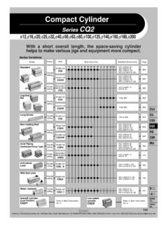
8 For faster speed, external stops with shockabsorption are required. These should be positioned to preventinternal contact between the piston and end 4: double acting non cushioned cylinderCushioned cylinders have a built in method of shockabsorption. Small bore light duty cylinders have fixed cushionswhich are simply shock absorbing discs fixed to the piston orend cover (Figure 5).Figure 5: Fixed cushion cylinderOther cylinders have adjustable cushioning. This progressivelyslows the piston rod down over the last part of the stroke bycontrolling the escape of a trapped cushion of air (Figure 6).The cushion action is covered in detail later (Figure 38).Figure 6: Adjustable cushion cylinderMAGNETIC CYLINDERSM agnetic cylinders have a band of magnetic material aroundthe circumference of the piston and are fitted with a non- magnetic cylinder barrel.
9 The magnetic field can be imaginedas the shape of a donut around the barrel. This will travel withthe piston as the piston rod moves in and out. By placingmagnetically operated switches on the outside of the barrel,one at each end for example, signals will be received eachtime the piston rod completes a stroke (Figure 7).Figure 7: magnetic cylinder RODLESS CYLINDERSFor some applications it is desirable to contain the movementproduced by a cylinder within the same overall length taken upby the cylinder body. For example, action across a conveyorbelt, or for vertical lifting in spaces with confined novel design of a rodless cylinder is ideal in thesecircumstances. The object to be moved is attached to acarriage running on the side of the cylinder barrel. A slot, thefull length of the barrel, allows the carriage to be connected tothe piston.
10 Long sealing strips on the inside and outside of thecylinder tube prevent loss of air and ingress of dust. The slot isunsealed only between the lip seals on the piston as it movesbackwards and forwards (Figure 8). Direction and speedcontrol is by the same techniques as applied to 8: Rodless cylinderROTARY ACTUATORST here are many applications that require a turning or twistingmovement such as turning components over in a drilling jig orproviding a wrist action on a pick and place device. Rotaryactuators provide angular rotation up to 360 . A typical rotaryvane design is shown in (Figure 9).Figure 9: Rotary vaneS6 Another form of rotary actuator is the rack and pinion basic double acting rack and pinion design is shown in(Figure 10). These larger actuators are often used in theprocess industry to operate quarter turn 10: Rack and pinionThe torque output can be doubled by adding a second actuatorto drive the same pinion (Figure 11).