Transcription of The Tendency for Freckle Formation in Alloy 718
1 THE Tendency FOR Freckle Formation IN Alloy 718 IS. Morita*, T. Suzuki*, T. Taketsuru*, D. G. Evans**, W. Yang** * Daido Steel Co., Ltd., Nagoya, Japan ** Special Metals Corporation, New Hartford, NY Abstract Solidification macro-segregation, particularly in the form of freckles, in nickel base superalloys is the main cause for the limitation of the ingot diameter and melting rate during vacuum arc remelting (VAR) and electro-slag remelting (ESR) process. The critical solidification conditions for Freckle Formation in Alloy 71 8 were studied by horizontal directional solidification (H-DS) experiments under various solidification conditions, and validated by commercial sized VAR ingots. The Tendency for Freckle Formation in this Alloy was evaluated by an expression based on the Rayleigh criterion including solidification rate, thermal gradient in the mushy zone, and solidification front angle to the horizontal plane. In order to systematize the methods to predict proper VAR operating conditions for any Alloy and ingot diameter, a solidification simulation approach has been developed based on the results of the above trials.
2 Introduction Recently, superalloy producers have been required to produce vacuum arc remelting (VAR) and electro-slag remelting (ESR) ingots, which has larger diameter in some types of alloys , because of the stronger demand than ever for the scale-up of the aircraft engines and land-based gas turbines. However, solidification macro-segregation, particularly in the form of freckles, in the nickel base superalloys is one of the main cause for the limitation of the ingot diameter and melt rate during these processes, and it has not been completely systematized yet. Freckle is a kind of macro-segregation, which can be seen as liner trails of equiaxed grains with eutectic constituents along the vertical plane around the mid-radius region in remelted ingots, and which is undesirable in any application because of their unremovability by any thermal or mechanical treatments after remelting process. Freckle defects are believed to be generated as a result of thermosolutal convection against the dendrite arm resistance, which is caused by the density inversion in the mushy zone.
3 Therefore, Tendency of Freckle Formation is strongly influenced by density change during solidification and dendrite arm geometry (spacing and direction). In other words, the Tendency can be expressed by a combination of the chemical composition effect term and solidification conditions effect term. In order to exterminate freckles with minimum risk and cost in remelted ingots, first of all, the critical solidification conditions, cooling rate; V (Us), solidification rate; R (rn/s), thermal gradient; G (Wm), and solidification front shape for Freckle Formation ; 0 (degrees) in Alloy 718 were investigated using horizontal directional solidification (H-DS) experiments. Then, the critical value for Freckle Formation obtained from the H-DS experiments was evaluated by investigating commercial sized ingots. For the evaluation, an expression based on the Rayleigh criterion including solidification rate, thermal gradient, and solidification front angle to the horizontal plane was developed and applied.
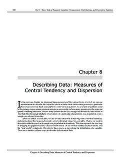
4 Finally, based on the results of the Superalloys 718, 625, 706 and Various Derivatives Edited by Loria TMS (The Minerals, Metals & Materials Society), 2001 above trials, a solidification simulation approach that make it possible to predict solidification conditions in remelted ingots, proper operating conditions of remelting process, has been developed and demonstrated. Experimental Methodology H-DS Experiments The schematic diagram of the horizontal directional solidification (H-DS) furnace is presented in Figure 1. First of all, the raw materials are melted by an induction furnace. Then, the molten metal is cast into the crucible of the H-DS furnace via the tundish. Before casting, the furnace temperature is controlled at 1773 K (1 500" C) for several hours for drying crucible. After casting alloys , the temperature and solidification direction are controlled by SIC heating elements, which are settled on three sides, and the cooling block, which is settled on the other one side.
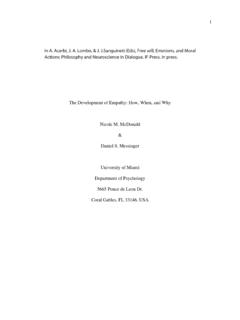
5 The temperature change of the molten metal is monitored by several thermocouples settled along the ingot centerline. The solidification direction has some degrees to the horizontal plane because of the imperfection of the top cover. The arrangement of the cooling block and the crucible set-up also make it possible to change solidification direction. (See Figxe 2) The experimental conditions are summarized in Figure 2. Totally 6 H-DS trials for Alloy 718 were conducted in order to identify the critical conditions for Freckle Formation in this Alloy . To get extensive solidification rates data, the furnace temperature drop rates were controlled from -30 to -60 K per hour, and the temperature rises of the cooling water after cooling were controlled from 14 to 19 K by changmg the flux of the cooling water. To get extensive solidification directions, several arrangements of the cooling block and the crucible set-up were prepared (block variations; straight, angle, and "L" type, set-up variations; horizontal, and bending fonvard/backward).
6 I I fi [Side View] Figure 1 : Schematic diagram of the horizontal directional solidification furnace. Upper view and Side view. Furnace Cooling Water I I I i I I I Figure 2: H-DS experimental conditions for Alloy 71 8. [The arrangement of the cooling block] R3002; Straight, R20 10; Angle(20 ), R4007A; Slope(-1 5 ' ), R4007B; Slope(l5 " ), R4O 10A; "L" type (short), and R4O 10B; "L" type (long). VAR Experiments , Straight I Angle i (20" ) In VAR process, it is generally agreed that long local solidification time (LST) condition tends to generate freckles. There are three ways to lengthen the LST. First method is to keep high melt rate all over the remelting. Second is to deepen molten metal pool depth gradually by rapid increase of melt rate. Then, third is to deepen molten metal pool depth rapidly by changing arc behavior from constricted to diffuse type. Arc behavior in VAR is strongly influenced by CO pressure and electrode gap. Constricted arcs are stabilized by high CO pressures and long electrode gaps, and then molten metal would be shallow and off axis.
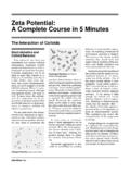
7 On the other hand, diffuse arcs are stabilized by low CO pressures and short electrode gaps, and then molten metal pool would be deep and symmetrical with the axis. It is found that there is a critical point, which is a transition in fluid flow from buoyancy to Lorentz as the melting current is increase from kA to kA ['I. In any case, freckles might be generated when the molten metal pool depth is deep enough or getting deeper. In other words, not to get any freckles in usual remelting, superalloy producers have been trying to keep low pressure, short electrode gap, and low and stable melt rate. Figure 3 shows the plan for Alloy 71 8. Because of the restriction of the VAR furnace, the first and second method to lengthen LST, rapid increase of current and keeping high melt rate, were applied to generate freckles. For this experimental, it was expected that darker part in this figures, the easier freckles would occur. The electrode conditions for the experiments are also shown in Table I.]
8 Slope (15" ) Slope (-15" ) Table I: Electrode conditions for Alloy 7 18 VAR experiment Item Alloy 7 1 8 Composition (%) Ni- 18Cr- Ti-5 2Nb Weight (kg) 1900 Diameter (mm) 3 80 Mold Diameter (mm) 457 Electrode Preparation .. VIM - -- - - VAR -.. - - Forge Initial=1470 " C ~A60" C/Hr i Water: i A14" C ~ "L" type (Short) Initial=l500 " C =A3O0 CIHr ?KG---/ water. A16" C] A16" C "L" type (Long) Initial=1470 " C _ 3 A 60 " CIHr Water: A19" C I Current 7 5kA I Figure 3: VAR experiments plan for Alloy 718. It was expected that darker part in this figure, the easier freckles would occur. Results and Discussion H-DS Experiments Temperature profiles The temperature and time data of H-DS trials are shown in Figure 4. The time in each graph is the time after casting (s), and temperature data in each graph is molten metal's temperature (K). In all trials, the temperature difference between near and far from the chill is seems to be big enough to get directionally solidified grains.
9 The averaged liquidus temperatures in H-DS trials are obtained. The liquidus of Alloy 71 8 is 1629K (1356a C). Figure 4: Temperature profiles in H-DS trials. Bottom side is the temperature data near the chill and topside is the temperature far from the chill. Solidification conditions In order to systematize the Tendency for Freckle Formation , all solidification conditions at 15 Kelvin below liquidus point (TL-15K) were selected for any calculation in this study, because TL-15K can be considered as Freckle 's initiation temperature '" 'I. The cooling rates (V, Ws) at TL-1 5K obtained from temperature data are shown in Figure 5. In all ingot, it is clear that the nearer the chill, the higher V before from the chill, however, it is not so clear after in most of the cases. It is because cooling effect of the chill was small at far from the chill, and there might be some cooling effect from the other side. It is found that V at TI--15K can be controlled from IUs ( ' Clmin) up to Kls (6' Clmin).
10 The correlation between R and G is shown in Figure 6. The absence and existence of freckles are divided by broken line. In the case of Alloy 718 at TL-ISK, it can be described as the equation, G = ( ~ 10-"/R. It is found that R at TL-15K can be controlled from " lo-' ds ( mmlmin) up to ~ 10-' mis ( mdmin), and G at TL-15K can be controlled up to 8000 Wm (8' Clmm). Because R and G in the typical industrial conditions are ~ 10-' to ~10-' mls (from to mmimin), and 500 to 4000 Wm (from to 4' Clmm), most of all industrial R and G region can be covered by H-DS trial. 0 12 Cooh rate 718. TL-1 5h -- C R2010 I I' 1 _ RW2 L 15 Freckle mtlation tenlpelatm RW-A L 15 0 1 = 0 2T,N 8T, Figure 5: Cooling rate in H-DS trials Figure 6: Solidification rate vs. Thermal Gradient in H-DS trials Macrostructure The example of macrostructure photographs and tracing of longitudinal and transverse cross sections of H-DS ingots is shown in Figure 7 (a), (b) and (c). In the tracing of the longitudinal cross section, the gravity direction is downward, broken lines indicate the grain direction, and solid lines with shadow indicate freckles on the surface.)