Transcription of The Three-Moment Equation for Continuous-Beam Analysis
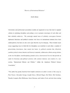
1 The Three-Moment Equation forContinuous-Beam AnalysisCEE 201L. Uncertainty, Design, and OptimizationDepartment of Civil and Environmental EngineeringDuke UniversityHenri P. GavinSpring, 2009 Consider a continuous beam over several supports carrying arbitrary loads,w(x).Using the moment -Area Theorem, we will analyze two adjoining spans of thisbeam to find the relationship between the internal moments at each of thesupports and the loads applied to the beam. We will label the left, center,and right supports of this two-span segmentL,C, andR. The left span haslengthLLand flexural rigidityEIL; the right span has lengthLRand flexuralrigidityEIR(see figure (a)).
2 Applying the principle of superposition to this two-span segment, we canseparate the moments caused by the applied loads from the internal momentsat the supports. The two-span segment can be represented by two simply-supported spans (with zero moment atL,C, andR) carrying the externalloads plus two simply-supported spans carrying the internal momentsML,MC, andMR(figures (b), (c), and (d)). The applied loads are illustratedbelow the beam, so as not to confuse the loads with the moment diagram(shown above the beams). Note that we are being consistent with our signconvention: positive moments create positive curvature in the beam.
3 Theinternal momentsML,MC, andMRare drawn in the positive directions. The2 CEE 201L. Uncertainty, Design, and Optimization Duke University Spring 2009 Gavinareas under the moment diagrams due to the applied loads on the simply-supported spans (figure (b)) areALandAR; xLrepresents the distance fromthe left support to the centroid ofAL, and xRrepresents the distance fromthe right support to the centroid ofAR, as shown. The moment diagramsdue to the unknown moments,ML,MC, andMRare triangular, as shown infigures (c) and (d).Examining the elastic curve of the continuous beam (figure (e)), we recognizethat the rotation of the beam at the center support, C, is continuous acrosssupportC.
4 In other words, Cjust to the left of pointCis the same as Cjust to the right of pointC. Thiscontinuity conditionmay be expressed LtanCLL= RtanCLR,(1)where LtanCis the distance from the tangent atCto pointL, and RtanCis the distance from the tangent atCto the second moment -Area Theorem, and assuming that the flexuralrigidity (EI) is constant within each span, we can find the terms LtanC,and RtanCin terms of the unknown moments,ML,MC, andMRand theknown applied loads. LtanC=1 EIL[ xLAL+23LL12 MCLL+13LL12 MLLL],(2)and RtanC=1 EIR[ xRAR+23LR12 MCLR+13LR12 MRLR].(3)Substituting these expressions into Equation (1) and re-arranging terms, leadsto the Three-Moment + 2(LLEIL+LREIR)MC+LREIRMR= 6 xLALLLEIL 6 xRARLREIR.
5 (4)Note that ifEIL=EIR=EI, the Three-Moment Equation is independent Three-Moment Equation was derived by Emile Clapeyron in 1857 using the differential equations ofbeam GavinStrain Energy in Linear Elastic Solids3 RtanCLLLCREIEIRLLRC+=+ tanCL3R(e)(c)(d)(b)(a)w(x)w(x)13 ALARLxRxMCMLL23RL2 MRL13 MLLL C Gavin4 CEE 201L. Uncertainty, Design, and Optimization Duke University Spring 2009 GavinTo apply the Three-Moment Equation numerically, the lengths, moments ofinertia, and applied loads must be specified for each span. Two commonlyapplied loads are point loads and uniformly distributed loads. For point loadsPLandPRacting a distancexLandxRfrom the left and right supports,respectively, the right hand side of the Three-Moment Equation becomes 6 xLALLLEIL 6 xRARLREIR= PLxLLLEIL(L2L x2L) PRxRLREIR(L2R x2R).
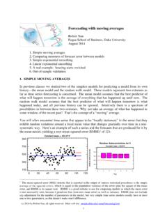
6 (5)For uniformly distributed loadswLandwRon the left and right spans, 6 xLALLLEIL 6 xRARLREIR= wLL3L4 EIL wRL3R4 EIR.(6)To find the internal moments at theN+ 1 supports in a continuous beamwithNspans, the Three-Moment Equation is applied toN 1 adjacent pairsof spans. For example, consider the application of the Three-Moment equationto a four-span beam. Spansa,b,c, anddcarry uniformly distributed loadswa,wb,wc, andwd, and rest on supports 1, 2, 3, 4, and Three-Moment Equation is applied to spansa b, spansb c, and spansc + 2(LaEIa+LbEIb)M2+LbEIbM3= waL3a4 EIa wbL3b4 EIbLbEIbM2+ 2(LbEIb+LcEIc)M3+LcEIcM4= wbL3b4 EIb wcL3c4 EIcLcEIcM3+ 2(LcEIc+LdEId)M4+LdEIdM5= wcL3c4 EIc GavinStrain Energy in Linear Elastic Solids5We know thatM1= 0 andM5= 0 because they are at the ends of the these end- moment conditions to the three Three-Moment equationsand casting the equations into matrix form, 10000 LaEIa2(LaEIa+LbEIb)LbEIb000 LbEIb2(LbEIb+LcEIc)LcEIc000 LcEIc2(LcEIc+LdEId)
7 LdEId00001 M1M2M3M4M5 = 0 waL3a4 EIa wbL3b4 EIb wbL3b4 EIb wcL3c4 EIc wcL3c4 EIc wdL3d4 EId0 .(7)The 5 5 matrix on the left hand side of Equation (7) is called aflexibil-ity matrixand is tri-diagonal and symmetric. This Equation can be writtensymbolically asF m=d. By examining the general form of this expression,we can write a matrix representation of the Three-Moment Equation for arbi-trarily many spans. If a numbering convention is adopted in which supportjlies between spanj 1 and spanj, the three non-zero elements in rowjofmatrixFare given byFj,j 1=Lj 1 EIj 1,(8)Fj,j= 2 Lj 1 EIj 1+LjEIj ,(9)Fj,j+1=LjEIj.
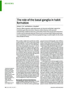
8 (10)For the case of uniformly distributed loads, rowjof vectordisdj= wj 1L3j 14 EIj 1 wjL3j4 EIj.(11)The moments at the supports are computed by solving the system of equa-tionsF m=dfor the Gavin6 CEE 201L. Uncertainty, Design, and Optimization Duke University Spring 2009 GavinOnce the internal moments are found, the reactions at the supports can becomputed from static 1j+1j 1jMMxxLPRPRxR/LjP/Lj 1 LxLM/Lj 1/Lj 1 MLj 1Lj"l""r"Pj 1wjw L /2jj 1wjjRLw L /2j 1j 1jMj 1jj/Ljj+1/Ljj+1 MMRj=12wj 1Lj 1+12wjLj+PLxLLj 1+PRxRLj MjLj 1 MjLj+Mj 1Lj 1+Mj+1Lj(12)where the first two terms on the right hand side correspond to a uniformlydistributed load and the next two terms correspond to interior point computed the reactions and internal moments, we can find the shearand moment diagrams from equilibrium equations.
9 For example, considerspanjbetween supportjand supportj+ 1. The internal shear force atsupportjin spanjisVj,j=Mj Mj+1Lj 12wjLj PkxkLj,(13)and the internal shear force at supportj+ 1 in spanjisVj+1,j=Mj Mj+1Lj+12wjLj+Pk 1 xkLj .(14) GavinStrain Energy in Linear Elastic Solids7 The termwjLj/2 in these two equations corresponds to a uniformly dis-tributed load,Pkis a point load within spanj, andxkis the distance fromthe right end of spanjto the point rotations at the supports may be computed from equations (1), (2),and (3). The slope of the beam at supportjis tan j. From the secondMoment-Area Theorem,tan j= 1 EIj 124wjL3j+16 PkxkLj(L2j x2k) +13 MjLj+16Mj+1Lj ,(15)where spanjlies between supportjand supportj+ 1.
10 The first term insidethe brackets corresponds to a uniformly distributed load. The second terminside the brackets corresponds to a point loadPkwithin spanj, located adistancexkfrom the right end of spanj, (supportj+ 1). Gavin8 CEE 201L. Uncertainty, Design, and Optimization Duke University Spring 2009 GavinThese ideas are implemented in [M,R,V,xs,M_Diag ,V_Diag ,d_Diag ,D_max] = three_moment(L,I,E,w,P,x)2% [M,R,V, xs , MDiag , VDiag , dDiag ,Dmax] = threemoment (L, I ,E,w,P, x )3% solve the three moment equations for a continuous beam of N spans .4%5% INPUT:6% L i s a vector of length N containing the lengths of each span.