Transcription of THERMODYNAMICALLY EFFICIENT DISTILLATION: ETHYLENE RECOVERY
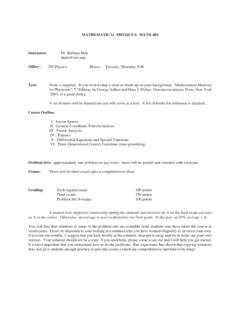
1 Page 1 of 6 Table 1 Feeds and Products for ETHYLENE + CFIGURE 1 MULTIPLE FEED DEMETHANIZER FIRSTDISTILLATION COLUMN SEQUENCEC4+DERC2 SDMRC3=C2C2=DPRFEEDC3SC3H2C1 THERMODYNAMICALLY EFFICIENT DISTILLATION: ETHYLENE RECOVERYD. B. MANLEYD epartment of Chemical Engineering, University of Missouri - RollaRolla, Missouri 65409, USAK eywords: Thermodynamics, Distillation, ETHYLENE , Olefins, SeparationsAbstractThe problem of recovering ETHYLENE and byproducts from the steam pyrolysis of light hydrocarbons is for improved efficiency using distributed distillation, recycle coupling, heat pumping, and mixedrefrigeration are presented. Emphasis is placed upon energy efficiency with potential savings in capital costs as appliedto refrigerated IntroductionSignificant savings in utilities may be achieved by using heatintegrated distillation in innovative configurations. On a percentagebasis, capital savings are somewhat smaller than utility savings; butthey are not negligible.
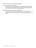
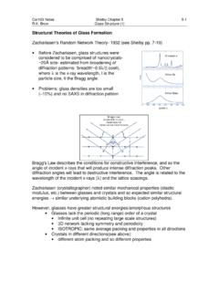
2 The improvements are at the expense ofincreased complexity, and incur the risk of new , conventional equipment may be used, and only theconfigurations innovative configurations may be generated by observingthermodynamic inefficiencies in conventional process are typically apparent in relationships between the primaryprocess variables such as temperature, pressure, and relationships may be observed through conventional analysissuch as McCabe - Thiele diagrams, composite heating and coolingcurves, and temperature - composition of the multiple products produced in the production ofethylene by steam pyrolysis of light hydrocarbons and because of thehigh pressures and low temperatures required for their RECOVERY , ETHYLENE manufacture provides several opportunities for economicalprocess improvements through improved thermodynamic Conventional ETHYLENE RecoveryTable 1 shows the feeds and products normally encountered inthe ETHYLENE RECOVERY process.
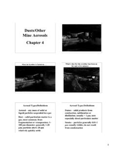
3 Both the gas (ethane) and liquid(naphtha) feeds contain about 31% ETHYLENE , but the light and heavybyproducts differ considerably. The pyrolysis reactions are favoredby low pressure. However, because of the low boiling points of theproducts, high pressures and low temperatures must be used for theirseparation by distillation. High purity is required for both theethylene and propylene products, and ETHYLENE and ethane havesimilar boiling points as do propylene and propane. As a result largediameter columns with many trays are required, and theseseparations are usually accomplished at the end of the recoveryprocess. The recovered products are produced at ambienttemperature and pressures sufficient for downstream processing orfor a 1 shows a conventional ETHYLENE RECOVERY distillationprocess (Kniel, et. al., 1980). The feed has been compressed,treated, dried, and partially hydrogenated to remove acetylene.
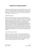
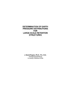
4 Partof the methane and all of the ETHYLENE and heavier components areseparated from the hydrogen and remaining methane bycondensation at low temperature. The liquids are then fractionatedunder pressure into products in demethanizer (DMR), deethanizer(DER), depropanizer (DPR), C2 splitter (C2S), and C3 splitter (C3S)distillation Thermomechanically Integrated DistillationAs discussed above the C2 and C3 splitter columns are largeand expensive, and accurate thermodynamic properties are necessaryfor their economical design. Figure 2 shows the relative volatility ofpropylene to propane on isotherms as functions of liquid phasecomposition. The logarithm of relative volatility is plotted becausePage 2 of Logarithm of Relative Volatility0 1 Mole Fraction Propylene in LiquidFigure 2 Propylene Propane Relative Volatility-20 F10 F40 F70 F100 F130 FFIGURE 3 THERMOMECHANICALLY INTEGRATEDOLEFIN / PARAFFIN SPLITTERFEEDPARAFFINREFRIGOLEFINit is closely related to the number of stages and the reflux required forthe separation.
5 At the high propylene end the relative volatilities aresmall, and they don t change much with temperature. This impliesthat reducing the column pressure, which also reduces thetemperature, will not reduce the column size significantly. However,at the high propane end the relative volatilities are larger, and theymay be increased significantly by reducing the column pressure. Thesame phenomenon occurs in the case of ETHYLENE and ethane becauseof the similar olefin / paraffin interaction between the analysis points toward using dual pressure columns for C2and C3 splitting with the stripping sections at a lower pressures thanthe rectifying sections. Normally, this would require an extracompressor which would be too expensive and unreliable. However,refrigeration or heat pumping, both of which require compression,must be used for C2 splitting anyway; and heat pumping may beused for C3 splitting. Consequently, there is an opportunity tocombine the compression functions using thermomechanicalintegration (Greene et.)
6 Al., 1994; Manley and Haddad, 1995) asshown in figure 3. The rectifying section in figure 3 is conventional. However, afew stages below the feed a heat pumped interreboiler is used topartially condense the overhead while simultaneously compressingthe vapors from the low pressure stripping section below. Asimilarly heat pumped reboiler is used to condense additionaloverhead vapors. Because the relative volatility of olefin to paraffinis much larger in the low pressure stripping section, significantly lessboilup is required, and more heat may be used in the interreboilerthan in a conventional, single pressure, column. The effect isenhanced because the olefin / paraffin ratios in the feeds generatedby pyrolysis are high by design to increase conversion. For a liquidoverhead product a small amount of addition refrigeration may benecessary to remove the energy required to drive the 4 summarizes the advantages of the more thermodynamicallyefficient 4 Advantages of Thermomechanically Integrated DistillationCLess compressor power than conventionally heat pumpedprocessCSmaller and lower pressure stripping sectionCCombined condenser / (inter)reboilerCEssentially independent of external refrigeration Distributed Distillation of EthyleneAnother inefficiency inherent in conventional ETHYLENE recoverymay be observed in figure 1 by keeping track of the phase changesnecessary to process the major ( ETHYLENE ) component.
7 Ethyleneenters the RECOVERY process as a gas, is condensed in thedemethanizer feed system, is revaporized in the deethanizer, and isfinally recondensed again as a liquid product from the C2 total of three complete phase changes must be accomplished forall the ETHYLENE . A similar analysis for other products yields similarconclusions. Propylene, for example, is condensed in thedemethanizer feed system, revaporized in the depropanizer, andrecondensed again as a liquid product from the C3 splitter. Are allthese phase changes really necessary?Figure 5 shows an ETHYLENE distributor column (Conroy , 1996) which separates methane from ethane in the presence ofhydrogen while distributing ETHYLENE between the overhead andbottoms products. A preliminary separation of the C3 and heaviercomponents is not shown in the figure. The ETHYLENE distributercolumn overhead is processed in a downstream demethanizercolumn, and the ETHYLENE distributor bottoms is processed in adownstream C2 splitter column.
8 In a properly designed processapproximately one half of the ETHYLENE in the feed will be distributedthrough the demethanizer and about one half will be distributedthrough the C2 splitter. However, the half which passes through thedemethanizer must be condensed only once since ETHYLENE productis produced in the demethanizer bottoms. Consequently, the totalnumber of phase changes necessary to produce the ETHYLENE productis reduced, and the thermodynamic efficiency of the process 3 of 6 FIGURE 5 DISTRIBUTED DISTILLATION OF ETHYLENEHYDROGENMETHANEETHYLENEETHANEHYD ROGENMETHANEETHYLENEETHYLENEETHANEETHYLE NEDISTRIBUTORHYDROGENMETHANEETHYLENEETHA NEDEMETHANIZERC2 SPLITTERSTAGE TEMPERATURE, DEG F-110-100-90-80-70-60-50-40-30-20 LIQUID PHASE MOLEFRACTION020806040100 FIGURE 6 ETHYLENE DISTRIBUTOR WITHOUT recycle COUPLINGETHYLENEETHANEMETHANEFIGURE 7 DISTRIBUTED DISTILLATION OF ETHYLENEWITH recycle COUPLINGHYDROGENMETHANEETHYLENEETHANEHYD ROGENMETHANEETHYLENEETHYLENEETHANEETHYLE NEDISTRIBUTORHYDROGENMETHANEETHYLENEETHA NEDEMETHANIZERC2 SPLITTERFIGURE 8 ETHYLENE DISTRIBUTOR WITH recycle COUPLINGSTAGE TEMPERATURE, DEG F-110-100-90-80-70-60-50-40-30-20 ETHYLENEETHANEMETHANELIQUID PHASE MOLEFRACTION0208060401005.
9 recycle CouplingFigure 6 shows the liquid composition profile for the ethylenedistributor column in figure 5. The feed at about -66oF is separatedinto ethane free methane and ETHYLENE on the top stage at about -70oFand into methane free ethane and ETHYLENE on the bottom stage atabout -29oF. However, because of the presence of hydrogen, thecondenser must cool the overhead to about -103oF in order togenerate the required reflux. This condensing process remixes methane and ETHYLENE , which have been more completely separatedat the entrance to the condenser; and they must then be reseparated in the downstream demethanizer column. A similar phenomenonoccurs to a lesser extent in the reboiler at about -28oF where ethaneand ETHYLENE are remixed and must then be reseparated in thedownstream C2 splitter mixing and separating occurring in the condenser andreboiler of the ETHYLENE distributor column may be eliminated byusing recycle coupling (Manley, 1996) as shown in figure 7.
10 Inthis case, the ETHYLENE distributor column is refluxed using a liquidsidedraw taken from the feed stage of the downstream demethanizer,and the ETHYLENE distributor column is reboiled using a vaporsidedraw taken from the feed stage of the downstream C2 splitter 8 shows the effect of recycle coupling on thecomposition profile in the ETHYLENE distributor column. Remixing iseliminated and consequently the separations required in thedownstream demethanizer and C2 splitter columns are figure 7 the ETHYLENE distributor condenser and reboiler fromthe figure 5 process have been replaced by an intercondenser on thedemethanizer and an interreboiler on the C2 splitter respectively. Thisallows the same utilities to be used in both cases. However, becauseof the improved thermodynamic efficiency when recycle coupling isused, the reflux and reboil flows in the demethanizer and C2 splitterare smaller in the case with recycle coupling.