Transcription of THROUGH-HOLE MICRO HEADER 8
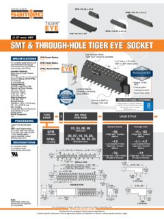
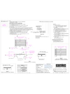
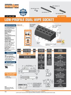
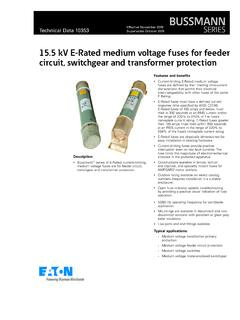
1 ( mm) .050"FTSH SERIESI mpedance matchedfor high-speed applications(Mated with CLP Series)Mates withsocket stripsor IDC cableThrough-hole, right-angle or surface mount( mm) .099"Optional endshrouds andejector shrouds( mm) .050" MICRO pitchFTSH 150 02 L DFTSH 115 03 L D RAFTSH 125 01 F DDue to technical progress, all designs, speci cations and components are subject to change without parts within this catalog are built to Samtec s speci speci c requirements must be approved by Samtec and identi ed in a Samtec customer-speci c drawing to ( ) .085( ) .200( ).126 ( ).440( ).120( ).075 DIA( ).090( ).090 ( ).050 A ( ).099 ( ).135010299100( ).090( ) .046 ( ).135 ( ).016 SQ( ).
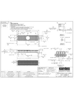
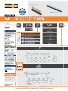
2 090 ( ).050 ( ).050 ( ) .050 No. of positions x ( ) .050 + Z( ).188100990201No. of positions x ( ) .050 ( ) .050 LEADSTYLENO. PINSPER ROW1 PLATINGOPTIONTAILOPTIONOPTIONOTHER OPTIONS RA EJ RA ES K ESFTSH D02 thru 50 ES= End Shroud(Style 02 & 03)9 pins/row min. EP= End Shroud with Guide Post(Style 02 & 03) 9 pins/row min. EL= End Shroud with Board Lock(Style 02 & 03)9 pins/row min. EJ= Ejector Shroud(Style 01 only)10 pins/row pins/row max. RA not available K= Keying Shroud for mating with FFSD (Style 01 only, 05, 08, 10, 13, 15, 17, 20 & 25 pins/row only and 13, 17, 20 & 25 only with EJ option)SpecifyLEAD STYLE from chart F= Gold flash on post, Matte Tin on tail L= 10 " ( m) Gold on post,Matte Tin on tailLeave blank for straight tail RA= Right- angle Leave blank for RIght-angle XXX = Polarized Position(Specify position of omitted pin)(Not available with -EX options)For complete specifications see Material:Black Liquid Crystal PolymerTerminal Material: Phosphor Bronze Plating:Sn or Au over 50 " ( m) NiCurrent Rating (FTSH/CLP) A per pin(2 pins powered)Operating Temp Range.
3 -55 C to +125 C RoHS Compliant:Ye sTHROUGH-HOLE MICRO HEADERLEAD STYLEAMATES WITH 01( ) .120 FFSD 02( ) .075 FLE 03( ) .065 CLP-D 04( ) .150N/AOPTIONZ ES( ) .061 EJ( ).621 EP( ) .231 EL( ) .257 EX OPTION SHOWN EL EPNotes: See SFM/TFM for positive alignment sizes, styles and options are non-standard, AVAILABLE(MOQ Required) Molded Pick & Place pads Other platingsFor complete scope of recognitions see CLIPFor single mating cycle with the -LC after tail option. Lead Style -01 and 10 pins/row minimum. 5-9 pins/row not availablein combination with keying shroud (-K).PCBOARD FFSDSTRIP ASSEMBLYLOCKINGCLIPFILE NO. E111594 PROCESSINGSPECIFICATIONSLead-Free Solderable: Yes Board Mates:CLP, FLEC able Mates:FFSD, FFTPEXTENDED LIFEPRODUCT10 YEAR MFGWITH 30 " GOLDHIGH MATINGCYCLESF-219 (Rev 16 APR19)