Transcription of Time Delay Relay Functions - Mouser Electronics
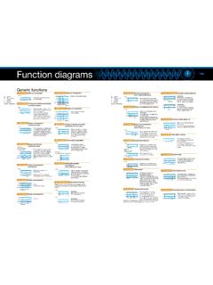
1 Make the most of your energySMTime Delay Relay FunctionsDetailed descriptions and timing chartsFunctionDescriptionTiming ChartRelaysOn Delay (A)The time Delay starts when applying the power supply and the output switches to the operate condition after the setting time has , 822, TDR782, TDRPRO-5100, TDRPRO-5101,TDRPRO-5102,TDRSOXR epeat Cycle: Starting Open(B)After a predetermined time , the output periodically switches on and off with substantially identical pulse on time and pulse off , 822, TDRPRO-5100, TDRPRO-5101,TDRPRO-5102,TDRSOXI nterval(C)The output immediately switches to the operate condition and the time Delay starts when applying the power supply, and the output switches to the release condition after the setting time has , 822, TDRPRO-5100, TDRPRO-5101,TDRPRO-5102 Repeat Cycle.
2 Starting Closed(F)The output immediately begins to switch off and on periodically with substantially identical pulse off time and pulse on , 822, TDRPRO-5100, TDRPRO-5101 Pulse Generator(G)The time Delay starts when applying the power supply; the output momentarily switches for an interval to the operate condition after the time Delay has , 822, TDRPRO-5100, TDRPRO-5101 Timing Chart KeyU = Input voltage (Power supply)R = Relay contactsT = Setting timeSchneider Electric - North American Operating Division1415 S.
3 Roselle RoadPalatine, IL 60067 Tel: 847-397-2600 Fax: 847-925-7500 Document Number 8501HO1001 2009 Schneider Electric. All rights ChartRelaysOff Delay (D)The output immediately switches to the operate condition when applying the power supply and the control signal; the time Delay starts when removing the control signal, and the output switches to the release condition after the setting time has , 822, TDRPRO-5100, TDRPRO-5101,TDRPRO-5102,TDRSRXR etriggerable One Shot(E)The output immediately switches to the operate condition and the time Delay starts when applying the power supply and the control signal.
4 The output switches to the release condition after the setting time has elapsed. Cycling the control signal during the time Delay will retrigger the time , 822, TDRPRO-5100, TDRPRO-5101,TDRPRO-5102,TDRSRXOne Shot(H)The output immediately changes to the operate condition and the time Delay starts when applying the power supply and the control signal; the output switches to the release condition after the setting time has elapsed. Cycling the control signal during the time Delay will not retrigger the time , 822, TDRPRO-5100, TDRPRO-5101On and Off Delay (I)The output switches to the operate condition when applying the power supply and the control signal and after the setting time has elapsed; the output switches to the release condition when the control signal is removed and after the setting time has , 822, TDRPRO-5100, TDRPRO-5101 Memory Latch(J)Upon application of the coil voltage, the Relay waits for trigger signaling.
5 The contacts transfer each time the trigger closes. There is no timing function involved ( flip-flop function).timeUSR821, 822, TDRPRO-5100, TDRPRO-5101 Timing Chart KeyU = Input voltage (Power supply)S = Switch trigger (Control switch)R = Relay contactsT = Setting timeMouser Electronics Authorized Distributor Click to View Pricing, Inventory, Delivery & Lifecycle Information: Schneider Electric: TDRSOXP-24V