Transcription of Title: ENGINE EVAP SYSTEM OPERATION EG002-01 …
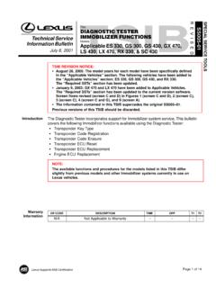
1 Toyota Supports ASE CertificationPage 1 of 11 Title: EVAP SYSTEM OPERATIONINFORMATIONM odels:All 96 01 ModelsTechnical ServiceInformation BulletinApril 27, 2001EG002-01 This service bulletin provides supplemental information regarding the SYSTEM design, OPERATION , and diagnostics of the Early Type (Non Intrusive) and Late Type (Intrusive)EVAP Systems found on 1996 model year and later OBD II equipped 300 EarlyEarlyEarlyEarlyLateLateGS 300N/AN/AEarlyEarlyEarlyLateGS 400N/AN/AEarlyEarlyEarlyN/AGS 430N/AN/AN/AN/AN/ALateIS 300N/AN/AN/AN/AN/ALateLS 400N/AN/AEarlyEarlyLateN/ALS 430N/AN/AN/AN/AN/ALateLX 470N/AN/AEarlyEarlyEarlyEarlyRX 300N/AN/AN/AEarlyLateLateSC 300N/AN/AEarlyEarlyLateN/ASC 400N/AEarlyEarlyEarlyLateN/AThis bulletin is divided into the following sections:Early Type and Late Type EVAP SYSTEM Outline1. Early Type DescriptionPages 2 4.. 2. Late Type DescriptionPages 4 5.. 3. Late Type SYSTEM Monitor Sequence Pages 6 8.
2 Diagnostic Tips For Late Type EVAP SystemPages 8 11.. OP CODEDESCRIPTIONTIMEOPNT1T2N/ANot Applicable to Warranty ENGINEI ntroductionApplicableVehiclesContentsWar rantyInformationEVAP SYSTEM OPERATION INFORMATION EG002-01 April 27, 2001 Page 2 of 11 Early Type (Non Intrusive) EVAP SYSTEM OverviewThere are a variety of EVAP systems in use with different monitoring strategies. It isessential that the EVAP SYSTEM be correctly identified before beginning diagnosis. TheRepair Manual is the best source for this information. The following information coversthe different first SYSTEM described is the Early Type (Non Intrusive) EVAP SYSTEM . Refer to theApplicable Vehicles chart for applicability Recovery Valve(Fill Check Valve)VaporPressureSensorVaporPressureSe nsorThree WayVSVV acuumCheckValveTank ValveAssemblyPressureValveCanisterToMani foldVacuumPurgeValveFilteredAirAir Drain ValveAir Valve AssemblyAir Inlet ValveAir Inlet LineServicePortPurge OperationWhen the ENGINE has reachedpredetermined parameters (closed loop, ENGINE temp.)
3 Above 125 F, etc.), storedfuel vapors are purged from the canisterwhenever the purge VSV is opened bythe ECM. At the appropriate time, theECM will turn on the purge ECM will change the duty ratio cycleof the purge VSV thus controlling purgeflow volume. Purge flow volume isdetermined by manifold pressure and theduty ratio cycle of the purge pressure is allowed into thecanister to ensure that purge flow isconstantly maintained whenever purgevacuum is applied to the canister (seeFigure 1).Early TypeSystemDescriptionFigure 1. Purge OperationFresh Air InletPurge VSVEVAP SYSTEM OPERATION INFORMATION EG002-01 April 27, 2001 Page 3 of 11 ORVR OperationDuring refueling, low pressure above thediaphragm in the onboard recovery valvelifts allowing fuel vapors into the charcoalcanister. At the same time, the air drainvalve opens and the charcoal absorbs thefuel vapors (see Figure 2).Early Type (Non Intrusive) EVAP SYSTEM DTCsEVAP Monitor Leak OPERATION P0440 The ECM tests for leaks by measuringEVAP SYSTEM pressure in the lines,charcoal canister, and fuel tank.
4 Whenthe EVAP pressure is higher or lower thanatmospheric pressure, the ECMconcludes that no leaks are pressure is measured by the vaporpressure sensor. If either the tank orcanister purge side is at atmosphericpressure under specific conditions, theECM determines there is a DTC P0440 is present, the leak is onthe fuel tank side of the EVAP also includes the lines between thefuel tank and part of the canister. Whenthe Vapor Pressure sensor is measuringtank pressure, the ECM is observingchanges in pressure and comparing tankpressure to atmospheric pressure. Nodifference in pressure indicates a ECM may take 20 minutes or more tocomplete testing the fuel tank side (seeFigure 3).Canister Leak Detection P0446 When the ECM switches the vaporpressure VSV to canister side, the ECMmeasures canister pressure. A leak onthe canister side can set multiple DTCs(see Figure 4).Early TypeSystemDescription(Continued)Figure 2.
5 ORVR OperationFigure 3. Fuel Tank Side of SystemFigure 4. Canister Side of SystemEVAP SYSTEM OPERATION INFORMATION EG002-01 April 27, 2001 Page 4 of 11 Vapor Purge Flow P0441 The EVAP monitor is designed to detect:SRestricted vapor purge flow when thepurge VSV is openSInappropriate vapor purge flow whenthe purge VSV is closedUnder normal purge conditions, pressurepulsations generated by the cycling of thepurge VSV are present in the canisterand detected by the Vapor Way VSV P0446 The three way VSV is connected to the Vapor Pressure sensor, canister, and fuel VSV allows the Vapor Pressure sensor to detect either canister or tank are two modes the ECM can use to determine if the three way VSV ismalfunctioning. The three way VSV is judged to be normal if there is pressure differencebetween the tank and canister when the three way VSV is switched to look at thecharcoal canister and fuel tank side of there isn t any pressure difference between the fuel tank and canister, the ECM looksfor the following conditions:SDuring purging, pressure pulsations generated by the purge VSV are not present inthe canister as detected by Vapor Pressure sensor, the three way VSV is judged tobe there are pressure pulsations detected by the Vapor Pressure sensor present in thefuel tank, the three way VSV is judged to be Type (Intrusive) EVAP SYSTEM OverviewThe Late Type EVAP SYSTEM , also known as the Intrusive type, was developed to meetthe very stringent, mandated standard of detecting a hole inch ( mm).
6 Thissystem uses many of the same components as the early type EVAP SYSTEM . Purge,vacuum relief, pressure relief, and ORVR operations are identical to the early type. Referto the Applicable Vehicles chart for applicability following changes were made to the Late Type EVAP SYSTEM :SVapor pressure sensor connected to the fuel VSV in the place of the three way Closed Valve (CCV) on the air inlet 5. Flow During Purge OperationEarly TypeSystemDescription(Continued)Late TypeSystemDescriptionEVAP SYSTEM OPERATION INFORMATION EG002-01 April 27, 2001 Page 5 of 11 Late Type (Intrusive EVAP SYSTEM )Onboard Recovery Valve(Fill Check Valve)VaporPressureSensorVacuumCheckValv eTank ValveAssemblyTankPressureValveCanisterTo ManifoldVacuumPurgeVSVF ilteredAirAir DrainValveAir Valve AssemblyAir Inlet ValveCanisterClosed ValveBypassVSVAir Inlet LineServicePortTank SideThe bypass VSV and the fill check valveassembly isolates the tank pressure sidefrom the canister side (see Figure 1).
7 Canister SideThe bypass VSV and the Fill Check valvealso isolate the canister side from thetank side (see Figure 2).Late TypeSystemDescription(Continued)Figure 1. Fuel Tank Side of SystemFigure 2. Canister Side of SystemEVAP SYSTEM OPERATION INFORMATION EG002-01 April 27, 2001 Page 6 of 11 Late Type (Intrusive) EVAP SYSTEM Monitor SequenceThe monitoring sequence for leak detection is different from that of the Early Type EVAPS ystem. The Late Type applies a very small vacuum to the EVAP SYSTEM . The ECM thendetermines if there is a problem in the SYSTEM based on the vapor pressure SequenceP0441P0440P0442P0446 CCV OpenPurge ClosedOpenClosedPurge ClosedOpenOpenCold Start ECT/IATNear Same TempNegativePressure(Vacuum)OccursLeak TestingPeriod OccursCCVOpOpenTime in MinutesBypass ClosedClosedBypassVSV OpVaporPressureSensor SignalMonitor OPERATION The monitor sequence begins with a coldengine start.
8 The IAT and ECT sensorsmust have approximately the sametemperature ECM is constantly monitoring fueltank pressure. As the temperature of thefuel increases, pressure slowly ECM will purge the charcoal canisterat the appropriate time (see Figure 1).With bypass VSV closed, pressure willcontinue to rise in fuel TypeSystemMonitorSequenceFigure 1. Canister PurgeEVAP SYSTEM OPERATION INFORMATION EG002-01 April 27, 2001 Page 7 of 11 Purge VSV OPERATION P0441At a predetermined point, the ECM closesthe CCV and opens the Bypass VSVcausing vacuum to increase in the entireEVAP ECM continues to operate the purgeVSV until the vacuum is increased to aspecified point at which time the ECMcloses the purge VSV (see Figure 2).If the vacuum did not increase, or if thevacuum increased beyond the specifiedlimit, the ECM judges the purge VSV andrelated components to be Detection P0440 and P0442 The rate of pressure increase as detectedby the vapor pressure signal indicates theif there is a leak and if it is a large orsmall purge valve OPERATION , the purgeVSV is turned off sealing the vacuum inthe SYSTEM and the ECM begins tomonitor the pressure increase (seeFigure 3).
9 Some increase is normal. Avery rapid, sharp increase in pressureindicates a leak in the EVAP SYSTEM andsets the DTC monitoring method is also able todistinguish what is called the small leakdetection. A pressure rise just abovenormal indicates a very small hole andwill set the DTC Control, CCV OPERATION P0446 This stage checks the CCV and vent (airinlet side) OPERATION . When the vaporpressure rises to a specified point, theECM opens the CCV. Pressure willincrease rapidly because of the airallowed into the SYSTEM . No increase oran increase below specified rate ofpressure increase indicates a restrictionon the air inlet TypeSystemMonitorSequence(Continued)Figu re 2. Vacuum ApplicationFigure 3. SYSTEM SealedFigure 4. CCV OpensEVAP SYSTEM OPERATION INFORMATION EG002-01 April 27, 2001 Page 8 of 11 Bypass VSV OPERATION P0446In the next stage, the ECM closes thebypass VSV. This action blocks airentering the fuel tank side of the pressure rise on the fuel tank side isno longer as great.
10 If there was nochange in pressure, the ECM willconclude the bypass VSV did not diagnostic process tests the EVAP SYSTEM . The following diagnostic tips may beused in conjunction with the Diagnostic Procedures for EVAP DTCs listed in the RepairManual. They may be used for all Late Type (Intrusive) EVAP Systems and for all EVAPDTCs. Refer to the Applicable Vehicles chart for applicability EVAP SYSTEM Pressure Test Kit (P/N 00002 6872A) and the Scan Tool can be usedto diagnose the EVAP SYSTEM . Measuring EVAP SYSTEM pressures using the EVAPS ystem Pressure Tester Gauge and the Scan Tool can aid in the identification of leaks inthe OutlineOnboard Recovery Valve(Fill Check Valve)ToManifoldVacuumFilteredAirPurgeVa lveCanisterClosedValveBypassValveAir DrainValveAir ValveAssemblyAir InletValveCanisterTank Pressure ValveVaporPressureSensorVacuumCheckValve Tank ValveAssemblyLate TypeSystemMonitorSequence(Continued)Figu re 5.