Transcription of Topic 14 - Foundation Design - Civil Engineering
1 Foundation Design 14-1 Instructional Materials ComplementingFEMA 451, Design ExamplesFOUNDATION DESIGNP roportioning elements for:Transfer of seismic forcesStrength and stiffnessShallow and deep foundationsElastic and plastic analysisFoundation Design 14-2 Instructional Materials ComplementingFEMA 451, Design ExamplesLoad Path and Transfer to SoilSoil PressureForce on a pileEQ on unloaded pilePile supporting structureInertial forceUnmoving soilEQ Motiondeflectedshapesoilpressuredeflecte dshapedeflectedshapesoilpressuresoilpres sureFoundation Design 14-3 Instructional Materials ComplementingFEMA 451, Design ExamplesLoad Path and Transfer to SoilSoil-to- Foundation Force TransferEQ motionPassive earthpressureFrictionShallowFoundation Design 14-4 Instructional Materials ComplementingFEMA 451.
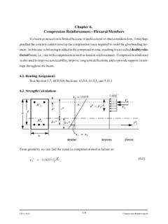
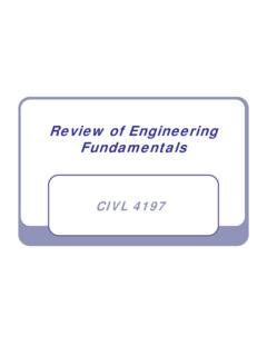
2 Design ExamplesLoad Path and Transfer to SoilSoil-to- Foundation Force TransferDeepEQ MotionMotionSoilpressureBendingmomentFou ndation Design 14-5 Instructional Materials ComplementingFEMA 451, Design ExamplesLoad Path and Transfer to SoilVertical Pressures - ShallowEQ motionOverturning momentFoundation Design 14-6 Instructional Materials ComplementingFEMA 451, Design ExamplesLoad Path and Transfer to SoilVertical Pressures - DeepEQ MotionOverturningmomentFoundation Design 14-7 Instructional Materials ComplementingFEMA 451, Design ExamplesReinforced Concrete Footings: Basic Design Criteria (concentrically loaded)d/2 (all sides)(c) Critical sectionfor two-way shear(b)Critical sectionfor one-way shear(a)Critical sectionfor flexureOutside face of concretecolumn or line midwaybetween face of steelcolumn and edge ofsteel base plate (typical)extent of footing(typical)dFoundation Design 14-8 Instructional Materials ComplementingFEMA 451, Design ExamplesFooting Subject to Compression and Moment: Uplift Nonlinear(a)Loading(b)Elastic, no uplift(c)Elastic, at uplift(d)Elastic, after uplift(e)Some plastification(f)Plastic limitMPFoundation Design 14-9 Instructional Materials ComplementingFEMA 451, Design ExamplesExample7-story Building.
3 Shallow foundations designed for perimeter frame and core Bays @ 25'-0" = 125'-0"1'-2"1'-2"7 Bays @ 25'-0" = 175'-0"1'-2"NFoundation Design 14-10 Instructional Materials ComplementingFEMA 451, Design ExamplesShallow Footing ExamplesSoil parameters: Medium dense sand (SPT) N = 20 Density = 120 pcf Friction angle = 33oGravity load allowables 4000 psf, B < 20 ft 2000 psf, B > 40 ftBearing capacity (EQ) 2000 Bconcentric sq. 3000 Beccentric = Design 14-11 Instructional Materials ComplementingFEMA 451, Design ExamplesFootings proportioned for gravity loads aloneCorner:6'x6'x1'-2" thickPerimeter:8'x8'x1'-6" thickInterior:11'x11'x2'-2" thickFoundation Design 14-12 Instructional Materials ComplementingFEMA 451, Design ExamplesDesign of Footings for Perimeter Moment Frame5 at 25'-0"7 at 25'-0"NFoundation Design 14-13 Instructional Materials ComplementingFEMA 451, Design Examples7-Story Frame, DeformedFoundation Design 14-14 Instructional Materials ComplementingFEMA 451, Design ExamplesCombining Loads Maximum downward + + E Minimum downward + E Definition of seismic load effect E.
4 E = 1QE1+ 2QE2+ x= y= and SDS= Design 14-15 Instructional Materials ComplementingFEMA 451, Design kA-5 EyExLiveDeadGridFoundation Design 14-16 Instructional Materials ComplementingFEMA 451, Design ExamplesReduction of Overturning Moment NEHRP Recommended Provisionsallow base overturning moment to be reduced by 25% at the soil- Foundation interface. For a moment frame, the column vertical loads are the resultants of base overturning moment, whereas column moments are resultants of story shear. Thus, use 75% of seismic vertical Design 14-17 Instructional Materials ComplementingFEMA 451, Design ExamplesAdditive Load w/ Largest Eccentricity At A5: P = ( ) + ( ) + ( ( ) + ( )) = 324 kMxx= ( ) + ( ) = -1106 k-ft At A6: P = ( ) + ( ) + ( ( ) + (-281)) = kMxx= ( ) + (-891) = -974 k-ft Sum Mxx= ( ) -1106 -974 = -7258 Foundation Design 14-18 Instructional Materials ComplementingFEMA 451, Design ExamplesCounteracting Load with Largest e At A-5:P = ( ) + ( ( ) + ( )) = kMxx= ( ) + ( ) = -1106 k-ft At A-6.
5 P = ( ) + ( ( ) + (-281)) = kMxx= ( ) + (-891) = -974 k-ft Sum Mxx= 6240 k-ftFoundation Design 14-19 Instructional Materials ComplementingFEMA 451, Design ExamplesElastic Response Objective is to set L and Wto satisfy equilibrium and avoid overloading soil. Successive trials usually Design 14-20 Instructional Materials ComplementingFEMA 451, Design ExamplesAdditive CombinationGiven P= 234 k, M=7258 k-ftTry 5 foot around, thus L= 35 ft, B= 10 ft Minimum W= M/(L/2) P= 181 k = 517 psfTry 2 foot soil cover & 3 foot thick footing W= 245 k; for additive combo use Qmax= (P+ )/(3(L/2 e)B/2) = ksf Qn= (3)Bmin= ksf, OK by ElasticFoundation Design 14-21 Instructional Materials ComplementingFEMA 451, Design ExamplesPlastic Response Same objective as for elastic response.
6 Smaller footings can be shown OK thus:PMWRLeRFoundation Design 14-22 Instructional Materials ComplementingFEMA 451, Design ExamplesCounteracting CaseGiven P= k; M= 6240 Check prior trial; W= 245 k (use ) e= 6240/( ) = > 35/2 NGNew trial: L= 40 ft, 5 ft thick W= 400 k; e= ft; plastic Qmax= ksf Qn= (3)4 = ksf, close Solution is to add 5 k, then e= ft and Qmax= Qn= ksfFoundation Design 14-23 Instructional Materials ComplementingFEMA 451, Design ExamplesAdditional Checks Moments and shears for reinforcement should be checked for the overturning case. Plastic soil stress gives upper bound on moments and shears in concrete. Horizontal equilibrium: Hmax< (P+W)in this case friction exceeds demand; passive could also be Design 14-24 Instructional Materials ComplementingFEMA 451, Design ExamplesResults for all SRS FootingsCorner: 10'x40'x5'-0" w/top of footing 2'-0" below gradeMiddle:5'x30'x4'-0" Side:8'x32'x4'-0" Foundation Design 14-25 Instructional Materials ComplementingFEMA 451, Design ExamplesDesign of Footings for Core-braced 7-story Building25 foot square bays at center of buildingFoundation Design 14-26 Instructional Materials ComplementingFEMA 451, Design ExamplesSolution for Central MatMat: 45'x95'x7'-0"with top of mat 3'-6" below gradeVery high uplifts at individual columns.
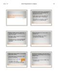
7 Mat is only practical shallow Design 14-27 Instructional Materials ComplementingFEMA 451, Design ExamplesBearing Pressure Solution(a)Plasticsolution(b)Elastic solutionpressures (ksf) ksf~Plastic solution is satisfactory; elastic is not; see linked file for more Design 14-28 Instructional Materials ComplementingFEMA 451, Design ExamplesPile/Pier FoundationsPassive resistance(see Figure )p-y springs(see Figure )PilecapPileView of cap with column above and piles Design 14-29 Instructional Materials ComplementingFEMA 451, Design ExamplesPile/Pier FoundationsPile Stiffness: Short (rigid) Intermediate LongCap influenceGroup actionSoil Stiffness Linear springs nomographs NAVFAC Nonlinear springs LPILE or similar analysisFoundation Design 14-30 Instructional Materials ComplementingFEMA 451, Design ExamplesSite Class E, depth = 10 ftSite Class E, depth = 30 ftSite Class C, depth = 10 ftSite Class C, depth = 30 resistance, p (lb/in.)
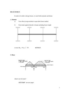
8 101001,00010, Pile deflection, y (in.) , p-yCurvesFoundation Design 14-31 Instructional Materials ComplementingFEMA 451, Design ExamplesPassive ult /H Design 14-32 Instructional Materials ComplementingFEMA 451, Design ExamplesGroup Effect1 2 Group effect 3 Group size (piles per side) 4s = Ds = 2 Ds = 3 Ds = 4 DFoundation Design 14-33 Instructional Materials ComplementingFEMA 451, Design ExamplesPile Shear: Two Soil Stiffnesses302520151050-5051015 Shear, V (kip)Depth (ft)Site Class CSite Class EFoundation Design 14-34 Instructional Materials ComplementingFEMA 451, Design ExamplesPile Moment vs Depth302520151050-1000-5000500 Moment, M ( )Depth (ft)Site Class CSite Class EFoundation Design 14-35 Instructional Materials ComplementingFEMA 451, Design ExamplesPile Reinforcement(4) #5#4 spiral at11 inch pitch(6) #5#4 spiral inch pitch(6)
9 #5#4 spiral inch pitch4" pile embedmentSection ASection BSection CCBA21'-0"23'-0"6'-4" Site Class C Larger amounts where moments and shears are high Minimum amounts must extend beyond theoretical cutoff points Half spiral for 3 DFoundation Design 14-36 Instructional Materials ComplementingFEMA 451, Design ExamplesPile Design (4) #7#4 spiral at11 inch pitch(6) #7#5 spiral inch pitch(8) #7#5 spiral inch pitch4" pile embedmentBA32'-0"20'-0"12'-4"Section ASection BSection CC Site Class E Substantially more reinforcement Full spiral for 7D Confinement at boundary of soft and firm soils (7D up and 3D down) Foundation Design 14-37 Instructional Materials ComplementingFEMA 451, Design ExamplesOther Topics for Pile foundations Foundation Ties: F =PG(SDS/10) Pile Caps: high shears, rules of thumb; look for 3D strut and tie methods in future Liquefaction: another Topic Kinematic interaction of soil layersFoundation Design 14-38 Instructional Materials ComplementingFEMA 451, Design ExamplesTie Between Pile Caps(2) #6 top bars(3) #6 bottom bars#4 ties at 7" " clearat sides3" clear attop and bottom Designed for axial force (+/-) Pile cap axial load times SDS/10 Often times use grade beams or thickened slabs one gra