Transcription of TRAILER BRAKE CONTROL MODULE INSTALLATION
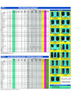
1 2010 F-150 Auxilliary BRAKE CONTROL Manual Table of ContentsTRAILER BRAKE CONTROL MODULE INSTALLATION CONTENTSINSTALLATIONT railer BRAKE CONTROL (TBC) ModuleGENERAL PROCEDURES Troubleshooting WIRING DIAGRAMS Relay Diagram Schematic Contents SKAL3J-19H332-AA Copyright Ford 2009 FoMoCo2010 F-150 Auxilliary BRAKE CONTROL 1 INSTALLATIONT railer BRAKE CONTROL (TBC) MODULE ItemPart NumberDescription1N807658 TRAILER BRAKE CONTROL (TBC) MODULE bolt (2 required)2 TBC MODULE connector (partof 14401)32C006 TBC module1 of 6 SKAL3J-19H332-AA Copyright Ford 2009 FoMoCo2010 F-150 Auxilliary BRAKE CONTROL 2 INSTALLATION (Continued)NOTE.
2 The TRAILER BRAKE system is normallyinstalled at the assembly plant, however, the systemcan be installed at the dealership but only if thevehicle is equipped with the TRAILER tow option. Thisoption can be confirmed by verifying the presenceof both the 4-pin and the 7-pin connectors at therear of the vehicle as well as a receiver hitch. If thevehicle is not equipped with these 3 items, then it isnot equipped with TRAILER tow and cannot have thefactory TRAILER BRAKE CONTROL (TBC)
3 Those vehicles equipped with the TRAILER towoption, the 14-way electrical connector for the the LH and RH floor console side trimmodule is attached to the back of the tray or taped to the 14401 harness Pull outward on the floor console side trimbehind the driver side knee bolster near the OBDII panels to release the retaining If the system is installed at the dealership,the TBC MODULE will be installed in place of the instrument panel-to-floor consolecoin bin/storage tray and the Instrument Cluster (IC)finish be configured to communicate with the TBCmodule.
4 Refer to the Wiring Diagrams manual, Using a non-marring tool, gently pryCell 95 TRAILER /Camper Adapter and Cell 151outward at the lower corners of theComponent Location Views for connector andinstrument panel-to-floor console finishwiring information. Refer to Programmablepanel to release the retaining in the Diagnosis and Testing portion ofthis section for information on IC the LH center instrument panel :Vehicles with selector lever in the parking the selector lever in the 1 the steering wheel the front seats Remove the floor console finish panel.
5 Lift the floor console finish panel upward the 2 floor console rear the retaining the front seats Remove the 2 floor console-to-instrument the LH floor console trim panelpushpin Open the floor console storage of 6 SKAL3J-19H332-AA Copyright Ford 2009 FoMoCo2010 F-150 Auxilliary BRAKE CONTROL 3 INSTALLATION (Continued) the selector lever trim the LH center instrument panel trimpanel.
6 Lift the selector lever trim panel upward, atthe locations indicated, to release the Pull the LH center instrument panel trimretaining toward the rear of the vehicle torelease the retaining clips. If equipped, disconnect the and save the two 7 mm bolts used tosecure the coin bin/storage and discard the coin bin/storage the TBC. Connect the electrical connector. Install two 7 mm battery charge relay 8L8T-14B192-AAand battery charge fuse 6E5T-14A094-BA, the 2 floor console front power distribution box located under thehood above the fan shroud.
7 (See the floor console , Click Here) the LH center instrument panel trimNOTE: Always verify proper operation of thepanel lower BRAKE controller before towing a circuits for the electronic BRAKE controller havealready been fused from the engine compartmentfuse box. If your TRAILER functions do not operateproperly, then DO NOT operate your vehicle untilcorrections are : Always check TRAILER and vehicle functions( , Stop, Turn Signal, Electric Brakes andRunning Lights) before operating your vehicle unplug the adapter from the TRAILER towharness before your TRAILER functions DO NOT operate properly,DO NOT operate your vehicle until corrections areAll.
8 1 Relay (8L8T-14B192-AA) & 1 the 2 instrument cluster finish panel(6E5T-14A094-BA) has been provided with tow kit for INSTALLATION . This relay and the instrument cluster finish be installed to the relay box, located in theengine compartment on top of the fan shroud, inorder for the TRAILER tow battery charge system tofunction of 6 SKAL3J-19H332-AA Copyright Ford 2009 FoMoCo2010 F-150 Auxilliary BRAKE CONTROL 4 INSTALLATION (Continued)
9 Reprogram The Instrument the LH center instrument panel trimpanel lower : The message center will display TBC Tighten to 10 Nm (89 lb-in).FAULT if it is receiving communications from theTrailer BRAKE CONTROL (TBC) MODULE , but has the floor console configured for a TRAILER BRAKE system. If themessage center displays TBC FAULT and there the 2 floor console front DTCs stored in the TBC MODULE , follow these Tighten to 10 Nm (89 lb-in).steps to verify and/or modify the TBC moduleprogrammable parameter in the Instrument the selector lever trim panel.
10 (IC). Press the selector lever trim panel down toengage the retaining the vehicle using the normal IntegratedDiagnostic System (IDS) the floor console storage Programming and press the check the 2 floor console-to-instrument MODULE Programming and press box. Tighten to 5 Nm (44 lb-in). Programmable Parameters and press thecheck the floor console finish panel. Push the floor console finish panel down Personality and press the check the retaining the on-screen the instrument panel-to-floor consolefinish : The scan tool will display eitherEQUIPPED or NOT EQUIPPED to the left the LH and RH floor console side trimTBC-IC.