Transcription of Transit Time Flow Meter - Coulton
1 Operator s ManualToll Free: 800-535-3569 Tel: 262-639-6770 TFX Ultra Transit time Flow MeterTFX Ultra O&M Rev 01/11 3 TABLE OF CONTENTSQUICK-START OPERATING INSTRUCTIONS .. 81 - Transducer Location .. 82 - Electrical Connections .. 93 - Pipe Preparation and Transducer Mounting .. 94 - Startup ..10 INTRODUCTION .. Versatility ..11CE Compliance ..12 User Safety ..12 Data Integrity ..12 Product Identifi cation ..12 PART 1 - TRANSMITTER Connections ..14 Line Voltage AC Power Connections ..15 Low Voltage AC Power Connections ..15DC Power Connections ..16 PART 2 TRANSDUCER INSTALLATION .. 1 - Mounting Location ..17 Step 2 - Transducer Spacing ..19 Step 3 - Entering Pipe and Liquid Data ..21 Step 4 - Transducer Mounting ..22V-Mount and W-Mount Installation ..23 DTTS/DTTC Small Pipe Transducer Installation ..24 Mounting Transducers in Z-Mount Confi guration ..26 Mounting Track Installation.
2 28 PART 3 - INPUTS/OUTPUTS .. mA Output ..29 Control Outputs (DTFXB Only) ..30 Frequency Output (DTFXB only) ..32RS485 ..34 Heat Flow (DTFXE only) ..354 TFX Ultra O&M Rev 01/11 PART 4 - STARTUP AND CONFIGURATION ..38 Before Starting the Instrument ..38 Instrument Startup ..38 Keypad Programming ..39 Menu Structure ..40 BSC Menu -- Basic Menu -- Channel 1 Menu ..51CH2 Menu -- Channel 2 Menu ..53 SEN Menu -- Sensor Menu ..55 SEC Menu -- Security Menu ..56 SER Menu -- Service Menu ..57 DSP Menu -- Display Menu ..61 PART 5 - ULTRALINK ..63 Introduction ..63 System Requirements ..63 Basic Tab ..65 Flow Tab ..67 Filtering Tab ..70 Output Tab ..72 Channel 1 - 4-20 mA Confi guration ..73 Channel 2 - RTD Confi guration (DTFXE Only) ..74 Channel 2 - Control Output Confi guration (DTFXB Only) ..76 Setting Zero and Calibration ..78 Target Dbg Data Screen - Defi nitions ..81 Saving Meter Confi guration on a PC.
3 82 Printing a Flow Meter Confi guration Report ..82 APPENDIX ..83 Specifi cations ..84 Menu Maps ..86 Communications Protocols ..89 Heating and Cooling Measurement ..96 TFX Ultra Error Drawings ..102 Brad Harrison Connector Option ..108K-Factors Explained ..109 Fluid Properties ..112 Symbol Explanations ..114 Pipe Charts ..115CE Compliance Drawings ..120 Limited Warranty and Disclaimer ..122 Waste Electrical and Electronic Equipment (WEEE) Directive ..122 Return of Equipment/Sales Information Contacts and Procedures ..123 TFX Ultra O&M Rev 01/11 5 FIGURESF igure - Transducer Mounting Confi gurations .. 8 Figure - Transducer Connections .. 9 Figure - Ultrasound Transmission ..11 Figure - TFX Transmitter Dimensions ..13 Figure - Transducer Connections ..14 Figure - AC Power Connections ..15 Figure - 24 VAC Power Connections ..15 Figure - DC Power Connections.
4 16 Figure Transducer Mounting Modes DTTN, DTTL, and DTTH ..20 Figure - Transducer Orientation Horizontal - Transducer Alignment Marks ..23 Figure - Application of Couplant ..23 Figure - Transducer Positioning ..24 Figure - Application of Acoustic Couplant DTTS/DTTC Transducers ..25 Figure - Data Display Screen ..25 Figure - Calibration Page 3 of 3 ..25 Figure - Calibration Points Editor ..25 Figure - Edit Calibration Points ..26 Figure - Paper Template Alignment ..27 Figure - Bisecting the Pipe Circumference ..27 Figure - Mounting Track Installation ..28 Figure - Z-Mount Transducer Placement ..28 Figure - Allowable Loop Resistance (DC Powered Units) ..29 Figure - 4-20 mA Output ..30 Figure - Switch Settings ..30 Figure - Typical Control Connections ..31 Figure - Single Point Alarm Operation ..31 Figure - Frequency Output Switch Settings.
5 32 Figure - Frequency Output Waveform (Simulated Turbine) ..33 Figure - Frequency Output Waveform (Square Wave) ..34 Figure - RS485 Network Connections ..34 Figure - Surface Mount RTD Installation ..35 Figure - RTD Schematic ..35 Figure - Connecting RTDs ..36 Figure - Insertion Style RTD Installation ..36 Figure - RTD Adapter Connections ..37 Figure - Keypad TFX Ultra O&M Rev 01/11 Figure - Data Display Screen ..64 Figure - Basic Tab ..66 Figure - Flow Tab ..68 Figure - Filtering Tab ..70 Figure - Output Tab ..72 Figure - Channel 2 Input (RTD) ..75 Figure - Channel 2 Output Choices ..76 Figure - Calibration Page 1 of 3 ..78 Figure - Calibration Page 2 of 3 ..79 Figure - Calibration Page 3 of 3 ..80 Figure - Menu Map -- 1 ..86 Figure - Menu Map -- 2 ..87 Figure - Menu Map -- 3 ..88 Figure - TFX Ultra Output Confi guration Screen ..97 Figure - RTD Calibration (Step 1 of 2).
6 98 Figure - RTD Calibration (Step 2 of 2) ..99 Figure - Control Drawing Barrier DTT Transducers ..102 Figure - Control Drawing Barrier DTT Transducers Flexible Conduit ..103 Figure - Control Drawing DTFXB (Class 1, Div II) ..104 Figure - Control Drawing (Class 1, Div II DC) ..105 Figure - DTFX (AC) Hazardous Area Installation ..106 Figure - DTFX (DC) Hazardous Area Installation ..107 Figure - Brad Harrison Connections ..108 Figure - CE Compliance Drawing For AC Powered meters ..120 Figure - CE Compliance Drawing For DC Powered meters ..121 TFX Ultra O&M Rev 01/11 7 TABLEST able - Piping Confi guration and Transducer Positioning ..18 Table - Transducer Mounting Modes DTTN, DTTL, and DTTH ..19 Table - Transducer Mounting Modes DTTS / DTTC ..20 Table - Dip Switch Functions ..30 Table - Specifi c Heat Capacity Values for Water ..46 Table - Specifi c Heat Capacity Values for Other Common Fluids.
7 47 Table - Specifi c Heat Capacity Values for Ethylene Glycol/Water ..47 Table - Exponent Values ..49 Table - DYNASONICS RTDs ..53 Table - Sound Speed of Water ..57 Table - Sample Substitute Flow Readings ..59 Table - Transducer Frequencies ..66 Table - Available Data Formats ..89 Table - TFX MODBUS Register Map for Little-endian Word Order Master Devices ..90 Table - TFX MODBUS Register Map for Big-endian Word Order Master Devices ..90 Table - MODBUS Coil Map ..90 Table - TFX BACnet Object Mappings ..91 Table - BACnet Standard Objects ..94 Table - Heat Capacity of Water ..100 Table - Standard RTD Resistance Values ..100 Table - TFX Ultra Error Codes ..101 Table - Fluid Properties ..113 Table - ANSI Pipe Data ..115 Table - ANSI Pipe Data ..116 Table - Copper Tube Data ..117 Table - Ductile Iron Pipe Data ..118 Table - Cast Iron Pipe Data.
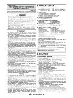
8 1198 TFX Ultra O&M Rev 01/11 QUICK-START OPERATING INSTRUCTIONSThis manual contains detailed operating instructions for all aspects of the TFX instrument. The following condensed instructions are provided to assist the operator in getting the instrument started up and running as quickly as possible. This pertains to basic operation only. If specifi c instrument features are to be used or if the installer is unfamiliar with this type of instrument, refer to the appropriate section in the manual for complete : The following steps require information supplied by the TFX Meter itself so it will be necessary to supply power to the unit, at least temporarily, to obtain setup - TRANSDUCER LOCATION1) In general, select a mounting location on the piping system with a minimum of 10 pipe diameters (10 the pipe inside diameter) of straight pipe upstream and 5 straight diameters downstream.
9 See Table for additional confi ) If the application requires DTTN, DTTL or DTTH transducers select a mounting method for the transducers based on pipe size and liquid characteristics. See Table Transducer confi gurations are illustrated in Figure : All DTTS and DTTC transducers use V-Mount confi ) Enter the following data into the TFX transmitter via the integral keypad or the ULTRALINK soft-ware utility:1. Transducer mounting method 7. Pipe liner thickness2. Pipe (Outside Diameter) 8. Pipe liner material3. Pipe wall thickness 9. Fluid type4. Pipe material 10. Fluid sound speed*5. Pipe sound speed* 11. Fluid viscosity*6. Pipe relative roughness* 12. Fluid specifi c gravity** NOMINAL VALUES FOR THESE PARAMETERS ARE INCLUDED WITHIN THE TFX OPERATING SYSTEM. THE NOMINAL VALUES MAY BE USED AS THEY APPEAR OR MAY BE MODIFIED IF THE EXACT SYSTEM VALUES ARE KNOWN. TOP VIEWOF PIPETOP VIEWOF PIPETOP VIEWOF PIPEW-MountV-MountZ-MountFIGURE - TRANSDUCER MOUNTING CONFIGURATIONS4) Record the value calculated and displayed as Transducer Spacing (XDC SPAC).
10 TFX Ultra O&M Rev 01/11 92 - ELECTRICAL CONNECTIONSTRANSDUCER/POWER CONNECTIONS1) Route the transducer cables from the transducer mounting location back to the TFX enclosure. Connect the transducer wires to the terminal block in the TFX ) Verify that power supply is correct for the meters power voltage AC units require 95 to 265 VAC47 to 63 Hz @ 17 VA voltage AC units require 20 to 28 VAC47 to 63 Hz @ A units require 10 to 28 VDC @ 5 Watts ) Connect power to the TFX fl ow - PIPE PREPARATION AND TRANSDUCER MOUNTING(DTTN, DTTL, and DTTH Transducers) 1) Place the fl ow Meter in signal strength measuring mode. This value is available on the TFX display (Service Menu) or in the data display of the ULTRALINK software ) The pipe surface, where the transducers are to be mounted, must be clean and dry. Remove scale, rust or loose paint to ensure satisfactory acoustic conduction.