Transcription of REX-C100/C400/C410/C700/C900 INSTRUCTION MANUAL
1 RKC INSTRUMENT Rights Reserved, Copyright 2012, RKC INSTRUMENT INC. Digital Controller REX-C100/C400/C410/C700/C900 INSTRUCTION MANUAL IMNZC22-E1 Thank you for purchasing this RKC product. In order to achieve maximum performance and ensure proper operation of your new instrument, carefully read all the instructions in this MANUAL . Please place the MANUAL in a convenient location for easy reference. To prevent injury to persons, damage to instrument and equipment, a suitable external protection device shall be required. All wiring must be completed before power is turned on to prevent electric shock, fire or damage to instrument and equipment. This instrument must be used in accordance with the specifications to prevent fire or damage to instrument and equipment. This instrument is not intended for use in locations subject to flammable or explosive gases.
2 Do not touch high-voltage connections such as power supply terminals, etc. to avoid electric shock. RKC is not responsible if this instrument is repaired, modified or disassembled by other than factory-approved personnel. Malfunction can occur and warranty is void under these conditions. This product is intended for use with industrial machines, test and measuring equipment. (It is not designed for use with medical equipment and nuclear energy.) This is a Class A instrument. In a domestic environment, this instrument may cause radio interference, in which case the user may be required to take additional measures. This instrument is protected from electric shock by reinforced insulation. Provide reinforced insulation between the wire for the input signal and the wires for instrument power supply, source of power and loads.
3 Be sure to provide an appropriate surge control circuit respectively for the following: - If input/output or signal lines within the building are longer than 30 meters. - If input/output or signal lines leave the building, regardless the length. This instrument is designed for installation in an enclosed instrumentation panel. All high-voltage connections such as power supply terminals must be enclosed in the instrumentation panel to avoid electric shock by operating personnel. All precautions described in this MANUAL should be taken to avoid damage to the instrument or equipment. All wiring must be in accordance with local codes and regulations. All wiring must be completed before power is turned on to prevent electric shock, instrument failure, or incorrect action.
4 The power must be turned off before repairing work for input break and output failure including replacement of sensor, contactor or SSR, and all wiring must be completed before power is turned on again. To prevent instrument damage as a result of failure, protect the power line and the input/output lines from high currents with a suitable overcurrent protection device with adequate breaking capacity such as fuse, circuit breaker, etc. Prevent metal fragments or lead wire scraps from falling inside instrument case to avoid electric shock, fire or malfunction. Tighten each terminal screw to the specified torque found in the MANUAL to avoid electric shock, fire or malfunction. For proper operation of this instrument, provide adequate ventilation for heat dispensation.
5 Do not connect wires to unused terminals as this will interfere with proper operation of the instrument. Turn off the power supply before cleaning the instrument. Do not use a volatile solvent such as paint thinner to clean the instrument. Deformation or discoloration will occur. Use a soft, dry cloth to remove stains from the instrument. To avoid damage to instrument display, do not rub with an abrasive material or push front panel with a hard object. When high alarm with hold action is used for Alarm function, alarm does not turn on while hold action is in operation. Take measures to prevent overheating which may occur if the control device fails. NOTICE This MANUAL assumes that the reader has a fundamental knowledge of the principles of electricity, process control, computer technology and communications.
6 The figures, diagrams and numeric values used in this MANUAL are only for purpose of illustration. RKC is not responsible for any damage or injury that is caused as a result of using this instrument, instrument failure or indirect damage. RKC is not responsible for any damage and/or injury resulting from the use of instruments made by imitating this instrument. Periodic maintenance is required for safe and proper operation of this instrument. Some components have a limited service life, or characteristics that change over time. Every effort has been made to ensure accuracy of all information contained herein. RKC makes no warranty expressed or implied, with respect to the accuracy of the information.
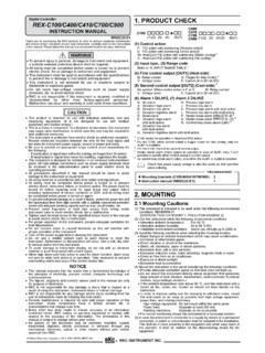
7 The information in this MANUAL is subject to change without prior notice. No portion of this document may be reprinted, modified, copied, transmitted, digitized, stored, processed or retrieved through any mechanical, electronic, optical or other means without prior written approval from RKC. 1. PRODUCT CHECK (1) Control action F: PID action with autotuning (Reverse action) D: PID action with autotuning (Direct action) W: Heat/Cool PID action with autotuning (Water cooling) 1 A : Heat/Cool PID action with autotuning (Air cooling) 1 (2) Input type, (3) Range code Refer to 9. INPUT RANGE TABLE. (4) First control output [OUT1] (Heat-side) M: Relay contact G: Trigger for triac driving 2 V: Voltage pulse 8: Current (4 to 20 mA DC) (5) Second control output [OUT2] (Cool-side) 3 No symbol: When control action is F or D.
8 M: Relay contact V: Voltage pulse 8: Current (4 to 20 mA DC) (6) Alarm 1 [ALM1], (7) Alarm 2 [ALM2] N: No alarm H: Process high alarm A: Deviation high alarm J: Process low alarm B: Deviation low alarm K: Process high alarm with hold action C: Deviation high/low alarm L: Process low alarm with hold action D: Band alarm P: Heater break alarm (HBA)[CTL-6] 4 E: Deviation high alarm S: Heater break alarm (HBA)[CTL-12] 4 with hold action R: Control loop break alarm (LBA) 5 F: Deviation low alarm with hold action G: Deviation high/low alarm with hold action 1 C100 cannot be specified in Heat/Cool PID action. 2 For the C100, when control output is trigger output for triac driving, only the ALM1 is available. 3 For the C100, there is no second control output.
9 4 Heater break alarm (HBA) cannot be specified in case of ALM1. Also, it isn t possible to specify when control output is current output. 5 As control loop break alarm (LBA), only either the ALM1 or ALM2 is selected. Check that power supply voltage is also the same as that specified when ordering. 2. MOUNTING Mounting Cautions (1) This instrument is intended to be used under the following environmental conditions. (IEC61010-1) [OVERVOLTAGE CATEGORY II, POLLUTION DEGREE 2] (2) Use this instrument within the following environment conditions: Allowable ambient temperature: 0 to 50 C Allowable ambient humidity: 45 to 85 % RH Installation environment conditions: Indoor use, Altitude up to 2000 m (3) Avoid the following conditions when selecting the mounting location: Rapid changes in ambient temperature which may cause condensation.
10 Corrosive or inflammable gases. Direct vibration or shock to the mainframe. Water, oil, chemicals, vapor or steam splashes. Excessive dust, salt or iron particles. Excessive induction noise, static electricity, magnetic fields or noise. Direct air flow from an air conditioner. Exposure to direct sunlight. Excessive heat accumulation. (4) Mount this instrument in the panel considering the following conditions: Provide adequate ventilation space so that heat does not build up. Do not mount this instrument directly above equipment that generates large amount of heat (heaters, transformers, semi-conductor functional devices, large-wattage resistors.) If the ambient temperature rises above 50 C, cool this instrument with a forced air fan, cooler, etc. Cooled air should not blow directly on this instrument.