Transcription of TRANSMISSION - Orange
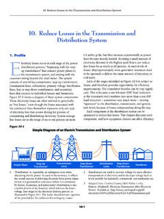
1 59 Chapter 6: TRANSMISSION and distribution Plan 2013-2022 Integrated Electricity Plan 2013 2022 TRANSMISSIONAND distribution PLAN 2013 2022 Chapter 6 The Mauritius electricity network is made up of the TRANSMISSION and distribution (T&D) systems, which are wholly owned and operated by the CEB. The TRANSMISSION network, operating at the highest voltage of 66 kV, transports power in bulk from the main sources of generation to various 66 kV-to-22 kV substations* scattered over the CEB s distribution system supplies electricity at lower voltages from its substations to various cus-tomers premises through 22 kV-to-415 V and kVto- 415 V distribution transformers. As at the end of 2011, the CEB s T&D assets were worth around Rs billion, reflecting the massive investment made in the electric network over the the size and importance of the network, it is imperative to ensure its proper management. Above all, the planning of the network is critical so that the CEB can support continuously the long-term social and economic developments of Mauritius and Ro-drigues.
2 The key objective of the electricity network planning is to determine the upgrading and expan-sion requirements of the electric network in order to guarantee the quality and reliability of electricity supply for the nation and the economic THE PRESENT TRANSMISSION AND distribution NETWORKIn a power system, the T&D network is the lifeblood of the system. In this section, a short conspicuous expos on the evolution of the CEB s T&D network is The CEB TRANSMISSION NetworkFigure in Chapter 4 illustrates the Mauritian trans-mission network, which consists of sixteen major substations and 300 kilometres of single-circuit trans-mission lines. The TRANSMISSION network is made up of a mix of underground cables and overhead lines. Overhead lines, which form around 94% of the net-work, greatly predominate because of their practical-ity and lower costs. Although they are more costly, underground cables are generally installed in places where there are environmental, or other, concerns.
3 The supporting structures of overhead lines, trans-mission- line towers and concrete poles are designed, among other standard design criteria, to withstand tropical cyclones having wind speeds within the range of 150 to 280 kilometres per hour. Part of the CEB s TRANSMISSION network has also been built for operation at 132 kV, when the need arises. In fact, in 1996, the final report for the project on Assistance in Generation and TRANSMISSION Plan-ning recommended introducing the 132 kV sys-tem voltage while retaining the 66 kV network as a sub- TRANSMISSION network. The recommendation was based on the assumption that all new genera-tion units would be centralised in the region of Port Louis. It was thus anticipated that the existing 66 kV TRANSMISSION capability would reach its limit dur-ing peak demand periods and, consequently, would require TRANSMISSION voltage upgrade to 132 kV by 2007. In the light of that recommendation, the 132 kV double-circuit TRANSMISSION lines were built.
4 However, moving towards the higher TRANSMISSION voltage level would require additional investment in 132 kV-to-66 kV power transformers, protective relays, 132 kV gas-insulated switchgears* and train-ing of the CEB s technical staff. Space requirement for the installation of the 132 kV equipment was al-ready catered for at the Saint-Louis, Ebene, Amaury, Wooton, Dumas and the future L Avenir substations, which would form part of the 132 kV TRANSMISSION network backbone. `* See glossary60 Subsequently, by adopting the decentralised genera-tion expansion approach, CEB took the strategic deci-sion to defer the upgrading of the TRANSMISSION net-work to 132 kV. Under this new approach, new power stations - the CTDS and the CTSav power Plants in the South, FSPG and CEL power Stations in the East and the CTBV power Plant in the North - were constructed to meet the increasing power demand*. distribution NetworkToday, CEB delivers electricity to approximately 422,000 customers across the island through its distribution system, which operates at medium voltages of 22 kV and kV and low voltages of 230 V single-phase and 400 V three-phase.
5 As at 2011, CEB had approxi-mately 8,450 kilometres of electric distribution lines. The break-down of the line length, in terms of different voltages and types of cable, is shown in Figure distribution network consists of overhead lines and underground cables. In town centres, such as Port Louis, Curepipe, Vacoas, Quatre Bornes and Rose Hill, and where access to the construction of an overhead network is not practical, underground cables are , the flow of electricity in the distribution network was uni-directional from the CEB s substa-tions to its customers. Since 2011, the distribution system has undergone a major change as customers are henceforth able to generate their own electricity and export the excess to the distribution change in the distribution network structure presents new challenges for the CEB, in terms of the planning, design and operation of the network. To meet some of these challenges, CEB, after having elaborated the SSDG s Grid Code, is now in the pro-cess of developing a grid code for its 22 kV network.
6 These changes are considered as stepping-stones to-wards the setting up of a future Smart Grid*. A brief on the proposed Grid Code and the conceptual Mau-ritius Smart Grid is given in Section and Section power SYSTEM MODELING AND PLANNINGAs an electric network grows in dimension, its com-plexities and vulnerabilities also increase, albeit more than proportionately. Assessing the impact of chal-lenges on the CEB s power system requires the use of appropriate analysis power System Analysis ToolsCEB carries out detailed system studies ( power sys-tem modelling and analysis) using a licenced state-of-the-art simulation software. The software is used to its full capability to plan the national electric network so as to ensure quality and reliable electricity supply for the present and the future. The main functionalities of the software used for system planning exercises are shown in Figure power System ModellingPower system analysis and studies generally start with the formulation of appropriate mathematical models of the existing generation, TRANSMISSION and distribution systems.
7 These models, which form the foundation of simulation processes, are made up of mathematical equations representing the technical characteristics of each component of the power sys-tem. In fact, the said characteristics are usually ob-tained from, either manufacturer s datasheets, and/ or through test and field measurements. CEB, on its own, developed the generation and trans-mission ( power system) models of Mauritius and Load Flow Analysis* power Flow and Loading Conditions Voltage Profiles Reactive power Compensation*Fault level Analysis* Short Circuit Level Choice and upgrading of EquipmentStability Analysis* Integration of conventional generation units Integration of variable renewable sources of generation Determine the critical fault clearing timeFIGURE : Functionalities of Simulation Software61% LV (OH)2% L V (UG) kV (OH) 3%22 kV (OH) 29%22 kV (UG) 4%%OH Overhead, UG Underground2% L V (UG) kV (OH) 361% LV (OH)22 kV (OH) 29%22 kV (UG) 4%FIGURE : Voltage distribution at distribution kV (UG) 1% kV (UG) 1%Chapter 6: TRANSMISSION and distribution Plan 2013-2022 Integrated Electricity Plan 2013 2022* See glossaryRodrigues, which were initially used to perform only power flow and short circuit analyses.
8 In order to en-hance the power system model, in 2009, CEB sought consultancy services to develop comprehensive mod-els of control systems (voltage and frequency) of all power plants in Mauritius. Similarly, comprehensive control systems models of Rodrigues power plants were developed by in-house experts. The enhanced power system models now also enable transient stability , CEB has mathematical models of its power sys-tems which are more realistic. With these enhanced models, the level of confidence is substantially boost-ed when performing analysis and planning studies. Using these models, CEB is now able to assess better the potential impact of disturbances and integration of variable renewable power sources on the frequency and voltages of the power systems. The present devel-oped power system models had enabled the following advanced system studies: Re-development of the Fort Victoria power Station to accommodate six new generation units; System Impact Studies for the wind power integra- tion of MW at Plaine Sophie and 9 MW at Plaine des Roches; System Impact Studies for the wind power integra- tion of MW in Rodrigues; Re-development of the Saint-Louis power Station for addition of 4 to 6 generating units; Interconnection of a 100 MW power Plant at Pointe aux Caves; Interconnection of major loads, for example Baga- telle Mall, Cargo Freeport Zone at Plaisance, High- lands City, Jin Fei, Neotown, amongst others; Reactive power Compensation; and TRANSMISSION Voltage the increasing number of connected distribut-ed generation projects (SSDGs & MSDGs), CEB is extending the above system modelling approach to improve its distribution network planning.
9 However, extending this approach will require, upstream, the implementation of a Geographical Information Sys-tem (GIS)* of the whole electricity network. The GIS will be a support to the nascent Spatial Load Fore-cast*. The value added of a GIS is discussed further in Section Network Planning ProcessThe flowchart in Figure on the next page illustrates the network planning , network planning is the process of ensuring reliable flow of electricity at high voltage* from genera-tion sources to various substations and, ultimately, to end-users, after stepping down to low voltage level. The process of network planning is mainly dependent on inputs from the Load Forecast and Generation data from the SCADA* of the System Control Centre*, the process starts by validating the transmis-sion model so that it reflects the actual network oper-ating assess the impact of load growth and/or new gener-ation units on the TRANSMISSION network, inputs from the Spatial Load Forecast* and Generation Expansion Plan are used.
10 Using these inputs, simulations of the TRANSMISSION network for each planning year are per-formed so as to identify abnormal conditions, such as overloading, low and high voltage reinforcements are then developed to over-come these abnormalities and simulations are per-formed again in order to validate the proposed re-inforcements. In case more than one solution is technically feasible, the least-cost one is proposed for Planning CriteriaIn general, planning criteria are technical boundaries, defined in a Grid Code, within which an electrical sys-tem should operate so as to ensure the reliability andquality of electricity Planning CriteriaThe reinforcements of the TRANSMISSION system are guided by several factors, amongst others: power transfer requirements; Location and size of new major loads; Location and size of new generation units; Location and size of renewable generation sources; Expected retirement of existing generation units; Least-cost expansion of network, while minimising TRANSMISSION losses.