Transcription of WILLIAM V. TORRE APRIL 10, 2013
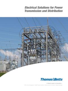
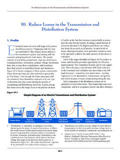
1 W I L L I A M V . T O R R E A P R I L 1 0 , 2 0 1 3 power System review Basics of power systems Network topology Transmission and distribution Load and Resource Balance Economic Dispatch Steady State System Analysis power flow analysis Dynamic System Analysis Transient stability Network Topology Transmission Lines High Voltage 69 kV 500 kV power Capacity 50 1,000 MW Carry power long distances P= 3 sin Low energy losses , Ploss= 2 Large structures power Transmission In the United States Network Topology distribution Circuits Primary; 12 34 kV AC Secondary: 480 V 120 V AC power capacity: 10 40 MW Shorter distances, higher losses Smaller overhead structures Underground Terminal equipment Transformers Capacitors Lightning arresters Switches Customer Load Customer power Residential Single phase, 220 120 V, resistive Commercial Three phase, 277 4,160 V, inductive Metering of power Consumption Conventional meters Automatic Metering Infrastructure (AMI, aka.)
2 Smart Meter) Demand Response Automatic Manual Generating Resources Different Types Fossil Fuel Hydroelectric Nuclear Geothermal Renewable Photovoltaics Solar Thermal Wind Bio-gas power System Summary Economic Dispatch of Generation What is economic dispatch? The operation of generation facilities to produce energy at the lowest cost to reliably serve consumers, recognizing any operational limits of generation and transmission facilities. (EPAct Section 1234) There are two fundamental components to economic dispatch: Planning for tomorrow s dispatch Dispatching the power system today Planning for Tomorrow Dispatch Scheduling generating units for each hour of the next day s dispatch Based on forecast load for the next day Select generating units to be running and available for dispatch the next day (operating day) Recognize each generating unit s operating limit, including its.
3 Ramp rate (how quickly the generator s output can be changed) Maximum and minimum generation levels Minimum amount of time the generator must run Minimum amount of time the generator must stay off once turned off Planning for Tomorrow s Dispatch Cont d Recognize generating unit characteristics, including: Cost of generating, which depends on: its efficiency (heat rate) its variable operating costs (fuel and non-fuel) Variable cost of environmental compliance Start-up costs Next day scheduling is typically performed by a generation group or an independent market operator Reliability Assessment For Dispatch Analyze forecasted load and transmission conditions in the area to ensure that scheduled generation dispatch can meet load reliably.
4 If the scheduled dispatch is not feasible within the limits of the transmission system, revise it. This reliability assessment is typically performed by a transmission operations group Dispatching the power System For Today Monitor load, generation and interchange (imports/exports) to ensure balance of supply and load Monitor and maintain system frequency at 60 Hz during dispatch according to NERC standards, using Automatic Generation Control (AGC) to change generation dispatch as needed Monitor hourly dispatch schedules to ensure that dispatch for the next hour will be in balance Monitor flows on transmission system Keep transmission flows within reliability limits Keep voltage levels within reliability ranges Take corrective action, when needed, by.
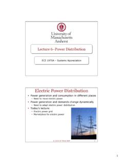
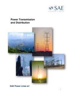
5 Limiting new power flow schedules Curtailing existing power flow schedules Changing the dispatch Shedding load This monitoring is typically performed by the transmission operator power Flow Analysis Assumes balanced three phase system Modeled as a single phase system A set of non-linear differential equations model both the Real (watts) and Reactive (Vars) power flow Matrices are developed for all impedances of transmission lines interconnecting substations (busses) Non-linear equations are solved through an iterative process, with an assumed initial conditions Three Phase AC power System Three phases oscillating at 60 Hz, 120 degrees out of phase EA EB EC Rotating Phasor Diagram of Waveforms 120 120 120 EA EC EB power System Electrical Components Resistance (Ohms) E=IR Inductance (Henry) Xl = 2 f* L, E= L(di/dt) Capacitance (Farads) Xc = 1/2 *C, I= C (dv/dt) Transmission Line Model These components can be modeled as a complex impedance Z, the inverse of Z is admittance Y Transmission Lines consist of series resistance, inductance, and capacitance power System Representation Links: Transmission Lines Nodes.
6 Buses (Substations) Generator Customer Loads Admittance Matrix We define: Ybus = [ Yij ] where Diagonal Elements: Off diagonal Elements: Note that Ybas matrix depends on the power grid topology and the admittance of all transmission lines. N is the number of busses in the grid. Admittance Matrix Example Example of Admittance Matrix for four bus example: After separating the real and reactive parts: Bus Voltage Let Vi denote the voltage at bus i Vi is a phasor with magnitude and angle power Flow Equations Substituting the admittance and voltage. The power flow equations become: We can solve these set of non-linear equations through iterative solution techniques Gauss-Seidel Method substitute voltages and solve equations, begin a new iteration using previously calculated voltages, until minimum tolerance is achieved Newton-Raphson Method faster iterative solution using Taylor series expansion Solution can be linearized, by making assumptions about suceptance, bus voltages, and power angle.
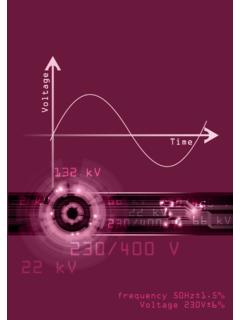
7 Faster solution, less accurate for reactive power values. power Flow Simulation Scenarios Maintenance or Force Outage Response: Loss of power line, calculate load flow and determine if overloads will occur, re-disptach generation or drop load Sudden Change in generation: Generation forced outage, Renewable Generation change, determine transmission line overloads, re-dispatch generation Others? Transient Stability Analysis of power Systems Same set of non-linear power equations as steady state power flow analysis Generator inertia and control system response is included Iterative time step solution is used to determine system response of each generator and active control loop Transient Stability Analysis power transfer equation: Equal Area Criteria for Transient Stability A1 must be less than A2 for the system to have a stable response Critical Clearing Angle Multi-Machine Stability Modern power systems are interconnected and operate close to their transient and steady state stability limits.
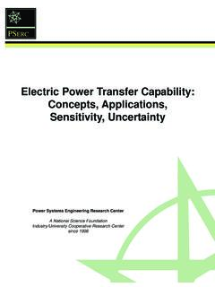
8 In large interconnected systems, it is common to find a natural response of a group of closely coupled machines oscillating against other groups of machines. Transient Stability Simulations Unstable Condition Poorly Damped Response Marginally Damped Response CCT= Critical Clearing Time Multi Machine Response February 26, 2013 Load Rejection Denver, Co power System Review Summary Transmission and distribution systems are extensive and complex Fundamental defining power system equations are non-linear and highly coupled Economic dispatch is becoming more difficult with additional renewable resources, due to uncertainty Transient Stability analysis is an important tool to ensure reliable power system operation Questions