Transcription of Trident Tritanium Acetabular System Surgical Protocol
1 OrthopaedicsTrident Tritanium Acetabular SystemSurgical ProtocolFor Crossfire and X3 Polyethyleneand Trident Alumina CeramicInserts With Tritanium Hemispherical Acetabular Shells1 OrthopaedicsTrident Tritanium Acetabular SystemSurgical ProtocolIndications Painful, disabling joint disease of the hipresulting from: degenerative arthritis,rheumatoid arthritis, post-traumaticarthritis or late stage avascular necrosis. Revision of previous unsuccessfulfemoral head replacement, cuparthroplasty or other procedure. Clinical management problems wherearthrodesis or alternative reconstructivetechniques are less likely to achievesatisfactory results. Where bone stock is of poor quality or isinadequate for other reconstructivetechniques as indicated by deficienciesof the Any active or suspected latent infectionin or about the hip joint. Any mental or neuromuscular disorderwhich would create an unacceptable riskof prosthesis instability, prosthesisfixation failure, or complications inpostoperative care.
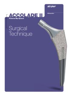
2 Bone stock compromised by disease,infection or prior implantation whichcannot provide adequate support and/orfixation to the prosthesis. Skeletal Crossfire and X3 Polyethyleneand Trident Alumina CeramicInserts With Tritanium Hemispherical Acetabular ShellsThis publication sets forth detailed recommended procedures for using Stryker Orthopaedics devices and instruments. It offers guidance that you should heed, but,as with any such technical guide, each surgeon must consider the particular needs of each patient and make appropriate adjustments when and as required. Seepackage insert for warnings, precautions, adverse effects and other essential product Trident Tritanium Acetabular System provides surgeonswith a highly porous ingrowth Trident Tritanium Acetabular System hemisphericalshells are manufactured from Commercially Pure Trident Tritanium shells utilize the screw hole patternand locking mechanism from the Trident Acetabular shells are available in sizes 48mm-80mm, and offer theoption of Alumina Ceramic or Crossfire or X3 polyethyleneinserts.
3 Refer to Table 1for insert and shell compatibility andsizing Alumina Ceramic Inserts gain fixation within the shellby means of mating tapers. Rotational stability between thecomponents is achieved when the shell s anti-rotational barbsinterlock with the insert s Trident AluminaCeramic Inserts must be used with Stryker OrthopaedicsAlumina Trident Polyethylene Inserts lock into the shell by meansof a circumferential ring that engages the shell s mating stability is achieved when the shell s anti-rotationalbarbs interlock with the insert s Trident Tritanium Acetabular System utilizes theCuttingEdge Total Hip Acetabular Instrumentation. Thissurgical technique is a guide to preparing the acetabulum for theTrident Tritanium Hemispherical Acetabular Tritanium Acetabular ShellCrossfire PolyethyleneInsert and X3 PolyethyleneInsert LFIT IonImplanted CoCrFemoral HeadTrident AluminaInsertAluminaFemoral HeadBiolox deltaFemoral HeadTrident Tritanium Acetabular SystemSurgical Protocol3 TABLE 1.
4 Trident Product Compatibility22mm Femoral Head , , , , , , , 76, 78, i d e n t Tritanium HemisphericalShell SizeAlphaCodeTrident X3 Crossfire 0 , 10 InsertPoly Thickness(mm)Eccentric InsertPoly Thickness(mm)Elevated RimInsert PolyThickness (mm)Tr i d e n t Alumina Ceramic 0 Inserts (mm)26mm Femoral Head , , , , , , , 76, 78, i d e n t Tritanium HemisphericalShell SizeAlphaCodeTrident X3 Crossfire 0 , 10 InsertPoly Thickness(mm)Eccentric InsertPoly Thickness(mm)Elevated RimInsert PolyThickness (mm)Tr i d e n t Alumina Ceramic 0 Inserts (mm)28mm Femoral Head , , , , , , , 76, 78, i d e n t Tritanium HemisphericalShell SizeAlphaCodeTrident X3 Crossfire 0 , 10 InsertPoly Thickness(mm)Eccentric InsertPoly Thickness(mm)Elevated RimInsert PolyThickness (mm)Tr i d e n t Alumina Ceramic 0 Inserts (mm)32mm Femoral Head Diameter50, , , , , , , 76, 78, i d e n t Tritanium HemisphericalShell SizeAlphaCodeTrident X3 Crossfire 0 , 10 InsertPoly Thickness(mm)Eccentric InsertPoly Thickness(mm)Elevated RimInsert PolyThickness (mm)Tr i d e n t Alumina Ceramic 0 Inserts (mm)36mm Femoral Head Diameter54, , , , , , 76, 78, i d e n t Tritanium HemisphericalShell SizeAlphaCodeTrident X3 Crossfire 0 , 10 InsertPoly Thickness(mm)Eccentric InsertPoly Thickness(mm)Elevated RimInsert PolyThickness (mm)Tr i d e n t Alumina Ceramic 0 Inserts (mm)10 ConstrainedInser t (mm)10 ConstrainedInsert OuterBearing Thickness (mm)10 ConstrainedInsertTotal Range of Motion10 ConstrainedInsert OuterBearing Thickness (mm)10 ConstrainedInsert OuterBearing Thickness (mm)10 ConstrainedInsert OuterBearing Thickness (mm)
5 10 ConstrainedInsertTotal Range of Motion10 ConstrainedInsertTotal Range of Motion10 ConstrainedInsertTotal Range of Motion10 ConstrainedInsertTotal Range of Motion10 ConstrainedInser t (mm)10 ConstrainedInser t (mm)10 ConstrainedInser t (mm)10 ConstrainedInser t (mm)10 ConstrainedInsert OuterBearing Thickness (mm)4 Trident Tritanium Acetabular SystemSurgical ProtocolFigure 1 preoperative Planning and X-ray EvaluationPreoperative planning and X-ray evaluation aids in the selectionof the most favorable implant style and optimal size for thepatient s hip pathology. Selecting potential implant styles andsizes can facilitate operating room preparation and assureavailability of an appropriate size selection. X-ray evaluationmay also help detect anatomic anomalies that could prevent theintraoperative achievement of the established preoperative a revision of an existing Acetabular shell is required, thesurgeon s preferred technique for removing the Acetabular shellshould be PreparationThe acetabulum is prepared by the release and removal of softtissue using the surgeon s preferred technique to gain adequateexposure for reaming.
6 Excision of the labrum and osteophytesallows for proper visualization of the bony anatomy, andimproves ease of Orthopaedics Retractors can be utilized to gainacetabular exposure (Figure 1).With the acetabulum exposed, bony defects, can be necessary, bone grafting options may be considered prior to ReamingTo obtain congruity in the reaming process, an optional 45/20 Abduction/Anteversion Alignment Guide can be attached to theCuttingEdge Reamer Handle (Figure 2). The alignment guide,when perpendicular to the long axis of the patient, will orientthe reamer handle at 45 of abduction, thereby placing the axisof the spherical reamer at 45 of inclination (Figure 3). Thereamer handle may then be positioned at 20 of anteversion byaligning the left/right anteversion rod on the alignment guide so that it is parallel to the long axis of the is recommended that initial reaming begin with a CuttingEdge Spherical Reamer that is 4mm smaller than the templated orgauged size.
7 The reamer is attached to the reamer handle bypushing down and applying a quarter-turn to lock in progresses in 1mm increments until final desired sizingis to the porous nature of the Tritanium coating, the outer diameter may be larger than the sizeindicated. The surgeon must consider this in the : Depending on bone quality and surgeonpreference, the surgeon may choose to ream line-to-line, or low profile design of the CuttingEdge Spherical Reamernecessitates reaming to the full depth. The reamer head shouldbe driven to the point where the rim/cross bar contacts theacetabular wall at the peripheral lunate region. Removal of thereamer from the handle is performed by pulling back on thelocking sleeve and rotating the reamer head a quarter-turn in a clockwise direction (Figure 4).Care should be taken so as not to enlarge or distort theacetabulum by eccentric reaming.
8 Final Acetabular reamingideally shows the hemispherical acetabulum denuded ofcartilage, with the subchondral plate preferably intact, and theanterior Acetabular wall is believed that the subchondral plate functions as animportant load-sharing and support mechanism. Preserving as much of the subchondral plate as possible may improve thequalities of the bone/metal : The CuttingEdge Spherical Reamers are veryaggressive and perform best when sharp. Care shouldbe taken to protect the reamer from unnecessaryhandling, as dull or damaged cutting teeth may causeimproper reaming. Dull cutting teeth will deflect tocut softer bone and resist hard bone. This situationmay result in an irregularly shaped or enlargedacetabulum 345 Figure 2 LockingSleeveFigure 46 Trident Tritanium Acetabular SystemSurgical ProtocolTrial EvaluationFollowing the reaming procedure, the appropriate Trident Tritanium Window Trial (Table 2), of the same diameter as thelast spherical reamer used, is threaded onto the CuttingEdge Shell Positioner/Impactor and placed in the acetabulum toevaluate the size and congruity of the preparation (Figure 5).
9 The trial is windowed for visualization and assessment of fit,contact and congruency of the trial within the acetabulum. Byinserting the Trident Trial Insert into the Trident Tritanium Window Trial (Figures 6 & 7), joint mechanics can be ensure that the Trial Insert is well fixed to the Trident Tritanium Window Trial during the trial evaluation, anAcetabular Trial Insert Containment Screw can be used. TheContainment Screw Kit (2230-0010) is optional (Figure 6). Thecontainment screw has a Torx drive feature and is compatiblewith Torx facilitate insertion/removal of the Trial Insert, holding forcepsmay be placed into the two holes in the plastic trialing, it is recommended to use a Trident Tritanium Window Trial 1mm-2mm smaller than the implant OD so as notto destroy the : The Window Trials (2208-40XX) specific to theTrident Tritanium Acetabular System must be Tritanium Trident Trial InsertWindow CompatibilityTrial (mm)Class46C47C48D49D50D51D52E53E54E55E5 6F57F58F59F60G61G62G63G64H65H66H67H68I69 I70I71I72J73J74J75J76J77J78J79J80 JFigure 7 RetainingRingTo r x ScrewFigure 6 Figure 5 TABLE 2.
10 Trident Tritanium WindowTrial/Trial Insert Sizing7 Trident Tritanium Hemispherical Shell ImplantationAfter completing the trial reduction, select the appropriatelysized implant desired, the CuttingEdge Abduction/Anteversion AlignmentGuide can be attached to the CuttingEdge Shell Positioner/Impactor to help establish the recommended 45 of abductioninclination and 20 of anteversion (Figures 8 & 9).Caution: Proper pelvic orientation is critical if relyingupon the CuttingEdge Alignment Guide to achievethe desired abduction/anteversion angles for metal shell is threaded onto the impactor at the threadedhole in the dome of the metal shell. It is important to fullyengage the threads and seat the impactor against the , the threads on the metal shell could becomedamaged, resulting in difficulty with the removal of the impactorfrom the cluster screw hole pattern holes are intended to be orientedsuperiorly (Figure 10).


