Transcription of Troubleshooting Guide Self-Adjusting Wall Switch Timer
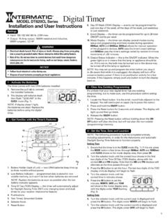
1 Connect the GREEN wire to the grounding screw in the box. If a plastic box, connect to ground as sure all twist connectors are a 3-Way Switch Setup:NOTE: The distance between Switch Timer and remote Switch must not exceed 100 feet. Locate the COMMON wire connected to first old Switch . It might be attached to a different colored screw, or find markings on old BLACK wire from Switch Timer to COMMON wire, using a twist the other two wires from the old Switch to the Blue and RED wires from the Switch the GREEN wire to the grounding screw in the box. If a plastic box, connect to ground as diagram #1 below. Identify and remove wire C from the Common terminal of your existing remote Switch .
2 Using diagram # 2 below, remove and reconnect wires B and C to the Common terminal of your remote Switch , using the supplied piece of jumper wire, if necessary. Follow diagram # 3 below, if using a new single-pole remote Switch . NOTE: For new construction or to replace a dimmer Switch , a lighted Switch , or a 3-way Switch without screw terminals, a single-pole Switch can be used at the remote location, as : If the building s wiring colors don t allow you to tell wire A from B, just pick one of the two wires and connect as if it is wire B. After the installation is complete, if the con-trolled light or device will not turn on properly, simply reverse wires A and B.
3 See Steps J and K for how to wires into the Timer wall box leaving room for the screws provided, mount the Switch Timer into the wall box, then install the wall the remote 3-way Switch in its box and install wall plate. Turn the power back on at the service sure the Switch Timer displays MAN mode. Do the fol-lowing test with the remote Switch in each of its 2 positions: Press the ON/OFF button on the Switch Timer several times. Each time that you push the ON/OFF button, the Switch Timer should click and the controlled light or device (the load ) should turn on or off. If so, proceed to Step the Timer clicks but the load does not operate, re-check your wiring and make sure the load is Wall Switch TimerTurn off power at the service panel by REMOVING FUSE or TURNING THE CIRCUIT BREAKER the existing wall building wires to 7/16 as a Single Switch Setup:Connect one of the two wires from the wall to the black wire from the Switch Timer , using the twist connectors provided.
4 Connect the other wire from the wall to the blue wire from the Switch Timer , using the twist connectors : The RED wire is not used in single- Switch installations. Cap with a twist (heater) 15 Amp, 120-277 VACT ungsten (incandescent) 15 Amp @ 120 VAC, 6 Amp @ 208-277 VACB allast (fluorescent) 8 Amp @ 120 VAC, 4 Amp @ 208-277 VACM otors 1 @ 120 VAC, 2 @ 240 VACDC Loads 4 Amp @ 12 VDC, 2 Amp @ 28 VDC Installation and User InstructionsMODEL ST01 Series2 Install the Switch TimerRatingsBefore installing the Switch Timer into the wall, make sure the supplied battery is installed and working. Open the access door to reveal the battery tray, located below the ON/OFF there is a pull tab at the battery tray, remove the tab to con-nect the installed battery.
5 Make sure battery tray is pushed fully into place. Proceed to Step the battery was supplied loose, use a flat screwdriver to pry loose the battery the supplied CR2 battery into the tray, observing + and markings on the battery tray into the Switch display will initialize itself then flash 12:00 AM in MANual the ON/OFF button. The Switch Timer should click. NOTE: If display doesn t flash 12:00 am , the battery may be dead. Replace the battery before installing the Switch Before Installing Switch Timer , Install and Check BatteryBLACK WIREBLUE WIRERED WIRE(capped, not connected)RED WIREBLUE WIREBLACK WIREWIRE FROM COMMON OFOLD SWITCH7/16 DIAGRAM 1:TYPICALEXISTING2-SWITCHSETUPLOADNEUTRA L3-WAY MAIN SWITCHWIRE A COMMON TERMINALLINE3-WAY REMOTE SWITCHWIRE B WIRE C DIAGRAM 2:2- Switch SETUP, Timer INSTALLRE-USING EXISTINGREMOTE 3-WAY SWITCHLOADNEUTRALWIRE A COMMON TERMINALLINE3-WAY REMOTE SWITCHWIRE B NOT USEDBLACKTIMERBLUEREDWIRE C JUMPERDIAGRAM 3.
6 2- Switch SETUP, Timer INSTALL USING NEW SINGLE-POLE REMOTE SWITCHLOADNEUTRALWIRE A LINESINGLE-POLEREMOTE SWITCHWIRE B BLACKTIMERBLUEREDWIRE C JUMPER158ST13133 Observed ProblemPossible CauseWhat to DoSwitch Timer does not Switch ON/OFF but display looks Timer is not set in AUTO, RANDom, or MANual MODE to select the operational mode you want to Timer won t enter AUTO or RANDom mode when you press time of day or Timer settings have not been sure the time of day and at least one sched-uled activity have been Timer switches at incorrect times or skips some of the programmed schedule(s) are ON/OFF to review the settings and revise them as necessary. See instructions at the Timer is in RANDom mode, which var-ies switching times up to 20 minutes (to give your home a lived-in look).
7 If you don t want to keep the Switch Timer in RANDom mode, press MODE to change to AUTO Astronomic and Specific switching times are in conflict. For example, you ve set ON to DUSK and OFF at 8 pm, and due to seasonal changes, DUSK has advanced to 8:30 pm. NOTE: Your Switch Timer automatically skips any conflicting ON event as summer ap-proaches to prevent unwanted operation of lights or other controlled devices. See What to Do if you want to identify and remove conflicting the steps for setting the Time and Date, then temporarily change the date to June the DAWN and DUSK settings by pushing the ON/OFF button. Make sure the specific ON or OFF time set-tings won t interfere with these DAWN and DUSK times.
8 Make changes as finished, change the Date setting back to today s date. lights or controlled devices don t match the programmed ON/OFF status immediately after setting the time or programming a Timer does not catch up automati-cally to the programmed load state. The status of the Switch Timer will remain as is until it comes to the next programmed ON/OFF entering your schedules or the time, then returning to the AUTO mode, push the ON/OFF but-ton to change the load state if only operates when the remote (3-way) Switch is in one position, or the Switch Timer ignores the remote remote Switch is wired the wiring, especially for the jumper, according to If a 3-way Switch Timer and If a Multiple Switch Timer Setup.
9 The Switch Timer ignores a 3-way remote Switch even though it is wired is an excessive length of wire (more than 100 feet), or there is buried wire to the the condition: either replace the buried cable, do without the remote Switch , or contact Intermatic Customer Service for more remote Switch is not functioning properly or worn the remote load turns off immediately after being turned remote Switch or Switch Timer is wired is an excessive length of wire (greater than 100 feet)There is buried wire to the remote Switch Timer is not functioning properly. If the problem persists with the Switch Timer s red wire disconnected or with a remote Switch tempo-rarily connected right at the Switch Timer , replace the non-functioning Switch Timer .
10 Otherwise, try the above battery tray is difficult to is not seated in the tray is contact tabs of the tray are bent. Seat the battery in the tray, then Switch Timer operation is sluggish or not switching ON/OFF at the BATT message is not being displayed, the battery is getting weak. Replace the battery. To test the battery, press the ON/OFF button. The Timer should click. Timer shows ON but the light or other controlled device is light or controlled device itself may be switched sure the light or controlled device is switched ON and plugged GuideLIMITED ONE-YEAR WARRANTYIf within one (1) year from the date of purchase, this product fails due to a defect in material or workmanship, Intermatic Incorporated will repair or replace it, at its sole option, free of charge.