Transcription of True-rms Multimeters - Fluke
1 PN 2572573 July 2006, Rev. 1, 2/07 2006, 2007 Fluke Corporation, All rights reserved. Printed in China All product names are trademarks of their respective companies. 114, 115, and 117 True-rms Multimeters Users Manual LIMITED WARRANTY AND LIMITATION OF LIABILITY This Fluke product will be free from defects in material and workmanship for three years from the date of purchase. This warranty does not cover fuses, disposable bat-teries, or damage from accident, neglect, misuse, alteration, contamination, or abnor-mal conditions of operation or handling. Resellers are not authorized to extend any other warranty on Fluke s behalf.
2 To obtain service during the warranty period, contact your nearest Fluke authorized service center to obtain return authorization information, then send the product to that Service Center with a description of the problem. THIS WARRANTY IS YOUR ONLY REMEDY. NO OTHER WARRANTIES, SUCH AS FITNESS FOR A PARTICULAR PURPOSE, ARE EXPRESSED OR IMPLIED. Fluke IS NOT LIABLE FOR ANY SPECIAL, INDIRECT, INCIDENTAL OR CONSEQUEN-TIAL DAMAGES OR LOSSES, ARISING FROM ANY CAUSE OR THEORY. Since some states or countries do not allow the exclusion or limitation of an implied warranty or of incidental or consequential damages, this limitation of liability may not apply to you.
3 Fluke Corporation Box 9090 Everett, WA 98206-9090 Fluke Europe Box 1186 5602 BD Eindhoven The Netherlands 11/99 1 True-rms Multimeters Introduction The Fluke Model 114, Model 115, and Model 117 are battery-powered, True-rms Multimeters (hereafter "the Meter") with a 6000-count display and a bar graph. This manual applies to all three models. All figures show the Model 117. These meters meet CAT III IEC 61010-1 2nd Edition standards.
4 The IEC 61010-1 2nd Edition safety standard defines four measurement categories (CAT I to IV) based on the magnitude of danger from transient impulses. CAT III meters are designed to protect against transients in fixed- equipment installations at the distribution level. Contacting Fluke To contact Fluke , call: USA: 1-888-99- Fluke (1-888-993-5853) Canada: 1-800-36- Fluke (1-800-363-5853) Europe: +31 402-675-200 Japan: +81-3-3434-0181 Singapore +65-738-5655 Anywhere in the world: +1-425-446-5500 Visit Fluke 's web site at Register your Meter at Unsafe Voltage To alert you to the presence of a potentially hazardous voltage, the Y symbol is displayed when the Meter measures a voltage 30 V or a voltage overload (OL) condition.
5 When making frequency measurements >1 kHz, the Y symbol is unspecified. Test Lead Alert XWWarning Personal injury or damage to the Meter can occur if you attempt to make a measurement with a lead in an incorrect terminal. To remind you to check that the test leads are in the correct terminals, LEAd is briefly displayed and an audible beep sounds when you move the rotary switch to or from any A (Amps) position. 114, 115, and 117 Users Manual 2 Safety Information A "XWWarning" statement identifies hazardous conditions and actions that could cause bodily harm or death. A "WCaution" statement identifies conditions and actions that could damage the Meter or the equipment under test.
6 To avoid possible electric shock or personal injury, follow these guidelines: Use the Meter only as specified in this manual or the protection provided by the Meter might be impaired. Do not use the Meter or test leads if they appear damaged, or if the Meter is not operating properly. Always use proper terminals, switch position, and range for measurements. Verify the Meter's operation by measuring a known voltage. If in doubt, have the Meter serviced. Do not apply more than the rated voltage, as marked on Meter, between terminals or between any terminal and earth ground. Use caution with voltages above 30 V ac rms, 42 V ac peak, or 60 V dc.
7 These voltages pose a shock hazard. Disconnect circuit power and discharge all high-voltage capacitors before testing resistance, continuity, diodes, or capacitance. Do not use the Meter around explosive gas or vapor. When using test leads or probes, keep your fingers behind the finger guards. Only use test leads that have the same voltage, category, and amperage ratings as the meter and that have been approved by a safety agency. Remove test leads from Meter before opening the battery door or Meter case. True-rms Multimeters Safety Information 3 Comply with local and national safety requirements
8 When working in hazardous locations. Use proper protective equipment , as required by local or national authorities when working in hazardous areas. Avoid working alone. Use only the replacement fuse specified or the protection may be impaired. Check the test leads for continuity before use. Do not use if the readings are high or noisy. Do not use the Auto Volts function to measure voltages in circuits that could be damaged by this function s low input impedance ( 3 k )(114 and 117 only). Symbols B AC (Alternating Current) I Fuse F DC (Direct Current) T Double Insulated X Hazardous voltage W Important Information; Refer to manual N Battery (Low battery when shown on the display.)
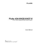
9 J Earth ground ~ Do not dispose of this product as unsorted municipal waste. Contact Fluke or a qualified recycler for disposal. D AC and DC 114, 115, and 117 Users Manual 4 Display VoltAlert117171812131496543211615810 Symbol Meaning Model A w The Meter is in the VoltAlert non-contact voltage detect mode. 117 B s The Meter function is set to Continuity. 114, 115, & 117 C R The Meter function is set to Diode Test 115 & 117 D O Input is a negative value. 114, 115, & 117 E Y X Unsafe voltage. Measured input voltage 30 V, or voltage overload condition (OL). 114, 115, & 117 True-rms Multimeters Display 5 F K Display hold enabled.
10 Display freezes present reading. 114, 115, & 117 G M VWX MIN MAX AVG mode enabled. Maximum, minimum, average or present reading displayed 114, 115, & 117 H (Red LED) Voltage presence through the non-contact VoltAlert sensor 117 I LoZ The Meter is measuring voltage or capacitance with a low input impedance. 114, 115 & 117 J n F mV A Mk kHz Measurement units. 114, 115, & 117 K DC AC Direct current or alternating current 114, 115 & 117 L N Battery low warning. 114, 115, & 117 M 610000 mV Indicates the Meter s range selection. 114, 115, & 117 N (Bar graph) Analog display. 114, 115, & 117 O Auto Volts Auto Manual The Meter is in the Auto Volts function.