Transcription of TST POWER KIT INSTALLATION INSTRUCTIONS
1 TST POWER KIT INSTALLATION INSTRUCTIONS Insure you have the tools/items listed below before disabling vehicle TST POWER Kit Fender covers to protect paint 7/16 inch deep barrel socket 3/8 s drive with ratchet 10 mm six point socket, 3/8 s drive with 3 extension Tape or clean towels to cover openings 7 mm and inch six point sockets, drive with 3 extension 19mm socket, 3/8 s or drive Center punch 8-10 inches long Hammer to strike punch and hand impact tool Hand impact tool, 3/8 s or drive T15 & T20 TORX bits drive with extension 6 long to 3/8 s and or adapter to hand impact tool 8mm 6point drive socket Large standard screw driver bit with 6 adapter for impact tool Large screwdriver or small pry bar Pliers 7/16 inch open end wrench 5/8 inch open end wrench Torque wrench capable of at least 30 pound-feet RTV silicon sealant 8 mm allen wrench 1. Park vehicle in a suitable work location, set parking brake, place automatic transmissions in park, manual transmissions in neutral, and open hood.
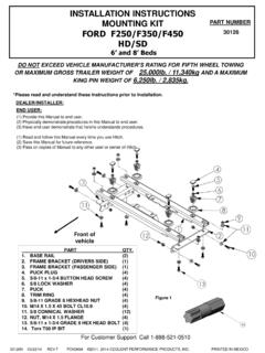
2 2. Disconnect both battery negative battery cables. 3. Clean engine if necessary to keep debris and foreign objects from entering engine 4. Place fender cover or protective covering to protect paint and batteries. 5. Using a 7/16 inch deep barrel socket, loosen lower clamp on upper intake connection hose and slide lower clamp off of hose and down the steel tube out of the way. (FIGURE 1) 6. Remove the six bolts holding the air intake connection and dipstick tube in place using a 10 mm 6 point socket. NOTE: Observe that these bolts are of different lengths so they can be installed in correct location during assembly. (FIGURE 1) 7. Remove intake manifold connection and hose as a unit, taking care not to damage gasket. This gasket can normally be reused however if it is torn, replace with a new gasket, Cummins part number 3913352. NOTE: Hold electrical grid heater in place while lifting the air connection so that the gasket joint under the grid heater is not disturbed.
3 8. Cover the air tube and manifold openings with tape or towels to keep foreign objects out. 9. Determine where your vehicle obtains its wastegate pressure signal. Some vehicles pick up this signal at an elbow on the front of the turbo as shown in FIGURE 2 while others get this signal at a tee connected to the rear of the injection pump as shown in FIGUREs 3 & 4. If your vehicle is like FIGURE 2 proceed to step 11 below. If your vehicle gets the wastegate signal from the tee at the rear of the injection pump, loosen the hose clamps on the AFC housing to turbo wastegate tube air hose using a 7 mm socket. Disconnect the hose from the barbed fitting on the top of the fuel pump Air Fuel Control (AFC) housing. Slide the hose as far as possible onto the steel turbo wastegate tube. 10. Remove the barbed fitting from the AFC housing using a 7/16 inch deep barrel socket.
4 NOTE: Save this fitting in case you want to convert your engine back to stock, this fitting is not used with the POWER Kit. 11. Remove injection pump fuel supply tube banjo bolt using a 19 mm socket. NOTE: A few ounces of fuel will drain out which could wash the sealing washers away. Take care NOT to loose sealing washers as they are reused. If lost or damaged replace with Cummins part number 3918192. NOTE: The fuel supply tube is not removed , loosening it on the injection pump end allows access to get to the AFC housing screws. OPTIONAL: You can avoid removing the banjo bolt if you bend the fuel supply line slightly so as to make access to the break off screw. (See FIGURE 4) This option saves some time, eliminates breaking into the fuel line, and make engine restart more quickly. 12. Next remove front passenger side AFC housing break off screw.
5 NOTE: This screw is a factory break off screw with rounded head and no screw driver, allen head or TORX slot. Use a hand impact tool with a 6 inch long extension and a T15 TORX bit to remove this screw. A center punch may be required to start a hole in the center of this screw. Set the hand impact tool in the removal position (counter clockwise) and use light hammer taps on the impact tool to loosen this screw. Tap progressively harder on the impact tool until the screw loosens. This method of removal forms a TORX shape into the screw allowing it to be reinstalled later with the T15 TORX bit. In some cases the hole in the top of this screw is too large for the T15 bit thus use the T20 TORX bit. There is usually a lock washer and flat washer under each of these screws.
6 OPTIONAL: A sharp chisel can be used to remove the break off screw by making a notch in the outside diameter of the head, then applying a tangential force with light blows to the chisel counterclockwise to remove the screw. 13. Use hand impact tool and a 8mm socket to remove the two driver side AFC screws. 14. Use the hand impact tool with large standard screw driver bit to remove the rear passenger side AFC screw. 15. Pry the fuel shutdown solenoid bracket away from the AFC housing using a larger screwdriver in the pry slot shown in FIGURE 4. This bracket only needs to move about 3/8 for clearance. FIGURE 1 FIGURE 2 FIGURE 3 FIGURE 4 16. Lift AFC housing, moving it out of the way toward the rear of the engine. The boost pressure line need not be disconnected. NOTE: Some engines have a metal rather than a plastic boost line between the engine intake to the AFC housing, in this case the boost line should be disconnected.
7 17. Place the INSTALLATION guide provided with the POWER Kit over the torque curve plate as shown in FIGUREs 5 and 6. This guide plate prevents objects from entering the open fuel pump and it helps position the new torque curve plate. NOTE: The INSTALLATION guide only fits one way, if it appears not to fit, flip it over and try again. 18. Leave one of the torque plate screws tight while removing the other screw using the hand impact tool with a large screw driver bit. Move the removed screw and reinstall it to one corner of the guide plate. Slide the INSTALLATION guide as far as possible toward the rear of the engine so that there is zero clearance between the front edge of the torque curve plate flange and the INSTALLATION guide, as shown in FIGURE 6. Once zero clearance is achieved, hand tighten the screw so that the guide does NOT move in the next four steps.
8 19. Remove the other torque plate screw and install it in another corner to help hold the guide in place. 20. Remove the stock torque curve plate using pliers or a magnet. Save the stock torque curve plate to permit converting the engine back to the stock rating in the future. 21. Place the new POWER Kit torque curve plate in the same position the stock plate formerly occupied, sliding the torque curve plate as far forward as possible so that there is near zero clearance left between the front of the torque plate and the INSTALLATION guide. 22. Install one of the two torque plate screws and hand tighten as tight as possible with a normal large screw driver. Install the 2nd screw. Using the hand impact tool and a large standard bit, tighten each screw another 1/8 to turn. 23. Remove INSTALLATION guide, save guide in case you want to convert the engine back to the stock.
9 24. Be sure that the AFC housing seal is in its groove (it may require a dab of grease or silicon sealant to hold it in place) then carefully reinstall the AFC housing. Do NOT force the housing into place, rather insure that the tang on the bottom of the housing fits in the slot in the torque curve plate. Wiring harnesses, hoses, and the solenoid bracket may need to be moved to get the housing to drop into its proper location. 25. Move the shutoff solenoid bracket back to its original position so that the AFC housing mounting screws will pass through the proper holes in the bracket and housing. 26. Install the AFC housing hold down screws loosely in their original locations, see FIGURE 4. A new break off screw is included in the POWER Kit if you want to replace the original break off screw. NOTE that the AFC housing mounting holes are slotted, slide the housing as far toward the front of the engine as the slots allow.
10 27. Tighten three of the AFC mounting screws (not the break off screw) as tight as possible with a normal screw driver, then use the hand impact tool to turn each screw and additional 1/8 to turn. It is suggested that you successfully complete the test drive before breaking off the head of the break off screw, only tighten it slightly to keep it from falling out during the test drive. You can reuse the original break off screw by installing with a TORX bit. 28. Install the turbo boost control (the small brass elbow supplied with the POWER Kit) into the 1/8 pipe port for wastegate control fitting (see FIGURE 4) in place of the barbed hose fitting removed in step 10. If your vehicle senses manifold pressure at the turbo as shown in FIGURE 2, remove the crimp type clamp with pliers, remove the stock elbow and install the boost control elbow from the POWER Kit in its place.