Transcription of TUB AND SHOWER VALVES - Moen Incorporated
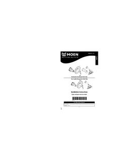
1 MT620 JMODELS 2290, 2291, 2600, 2700, 5401, 62600, 62700, 72615, 72700and MODEL SERIES T471, T473, T555, T666, T777 & T888 INSTALLATION INSTRUCTIONSTHESE INSTRUCTIONS MUST BELEFT WITH HOMEOWNERTUB AND SHOWER VALVESM easurementsT h e s e a r e s h o w n in t h e d r a w i n g s .T h e d e p t h m e a s u r e m e n t is c r i t i c a l . Usethe front face of the plaster ground as a reference point for the finishedw a l l p o s i t i o n , i n c l u d i n g t i l e ( 2 - 1 / 1 6 " [ 5 2 m m ] ) . T h e c e n t e r l i n e of t h e s u p p l ya n d d i s c h a r g e p i p i n g s h o u l d be a m a x i m u m of 2 - 3 / 1 6 " ( 5 6 m m ) a n d a m i n i m u mof 1-7/16" (37mm) behind the finished wall with three or four port castings, with and without are either 1/2 inch pipe or 1/2 inch copper sweat the Moen Slip Fit spout is used, a 1/2 inch copper drop and lookout may be :Always turn water off before disassembling the valve.
2 Open valve handle toalleviate water pressure to insure that complete water shut-off has turning water on during either rough-in or trim-out, make sure that cartridge retainer clip is in place. Thecartridge and retainer clip were properly installed and tested before leaving the factory. Although it is unlikely, it isnevertheless possible that through the handling of the valve by any number of persons the retainer clip may not bep r o p e r l y i n s t a l l e d . T h i s s h o u l d be c a r e f u l l y c h e c k e d at t i m e of r o u g h - i n a n d t r i m - o u t . If t h e r e t a i n e r c l i p is n o t p r o p e r l yinstalled, water pressure could force the cartridge out of the casting. Personal injury or water damage to thepremises could ASSEMBLYADJUSTABLETEMPERATURELIMIT STOPESCUTCHEONPLASTERGROUNDCAUTIONUSE 1/2"IRON PIPESIZEMINIMUMOR 1/2" "(1143mm)48"(1219mm)1-1/4"(32mm)6' 6"(1981mm)32"(813mm)FINISHED WALLLINE2-1/16"(52mm)2-1/16"(52mm)TUB FILLEROR SHOWERTUB/SHOWERCOMBINATIONFLOOR15/16"(2 4mm) CLIPEARUPIMPORTANT: SEE FLUSHINGINSTRUCTIONS PAGE 2 Stop OperationCC - This type is integral with casting, actuated by screwdriver, and require a 90 turn to open or close.
3 When the screwdriver slot is vertical, the rubberstop is closed, and when the slot is horizontal, the rubber stop is - This type has been added to the basic SHOWER casting and is actuated by screwdriver. The stop is opened by rotating in a counterclockwisedirection until it stops and closed by rotating in a clockwise direction until it port:(2700 SERIES): Install casting with "UP" at the top (arrow pointing up). If the valveis to be used for both a SHOWER and a tub, connect the top outlet to the SHOWER and the bottomoutlet to the tub, using 1/2" iron pipe size or 1/2" copper water tube, 5/8" (If the valve isto be used for a SHOWER only or a tub only, plug the outlet not being used.)3-port (2600 SERIES): These models may be used as either a SHOWER or a tub filler.
4 Sincethey are factory set in the SHOWER position, with the outlet up, you must reverse the position ofthe cartridge retainer clip if you want to use the valve as a tub filler. Following "Disassembly"instructions on page 3, pull the clip out from the bottom of the casting, rotate cartridge stem180 and replace clip in the top, then proceed with installation, using 1/2" iron pipe size or1/2" copper water : Secure all pipes and the SHOWER and tub drop ells. Use thread seal tape onall threads. U s e a p l a i n e l l on t h e t u b d r o p . A t w i n e l l is n o t n e e d e d . C h e c k s y s t e m f o r l e a k sbefore closing SURE ALL WATER SUPPLIES ARE VALVES are equipped withMoen's long-life 1225 cartridge , d e -signed for smooth, trouble freeoperation.
5 When soldering, donot heat valve any higher thannecessary t o flow t h e solder. Over-h e a t i n g m a y d a m a g e t h e c a r t r i d g eor rubber stop VALVES . Followingt h i s d i r e c t i o n w i l l a l l o w y o u to s o l -der without removing t h e cartridgeor rubber stop : T h e c a r t r i d g e a n d r u b -b e r s t o p v a l v e s M U S T be r e m o v e dbefore e i t her b razing o r resistance(electric) " DIA(178mm)SHOWERTUB2" CC(51mm)2-3/16" IPS(56mm)SUPPLYSUPPLY 7" DIA(178mm)SHOWERTUB2-1/8" CC(54MM)3-3/4" IPS(95MM)4-5/8" FOR (117mm)6" FOR (152mm)SUPPLYSUPPLY 4-1/2"(114mm)PLASTER GROUNDSIZE AND WALL OPENINGSPOTS HTIWSPOTS TUOHTIW RUBBER STOP VALVE(WITH SCREW DRIVER SLOT)FlushingIMPORTANT: Before closing all wall openings, pressure test valve and complete system forleaks using flushing.
6 Pipe chips, sand, stones, and other solids found in new or renovated plumbing can damage the sealing surface of the faucet cartridge and cause a avoid damage, DO NOT OPERATE VALVE until you have followed these instructions:1. After installing and connecting your new faucet, install SHOWER arm but not showerhead before Turn the valve on in the full cold position (handle pointing to the right) and turn on the cold supply for 15 seconds. Without closing the valve, turnto the full hot position (handle pointing to the left) and turn on the hot supply for 15 Turn the valve to the mixed position, divert water to the SHOWER and run for an additional 15 Turn off the water and check for Install "OFF" both hot and cold water supplies, then open faucet to relieve pressure.
7 Remove handle cover from handle knob. Take out handle screw andremove handle knob, washer, and stop tube. Lift out retainer clip. Rotate cartridge shell back and forth with Moen cartridge twist wrench, grasp the cartridgestem with pliers, and pull out the cartridge by pushing it all the way into the body until the front of the ears on the cartridge shell are flush and aligned with the body, (see illustration).Replace the retainer clip so that the legs straddle the cartridge ears and slide down into the bottom slot in the body. This prevents the cartridge from rotatingand locks it in the body. The notched flat on the stem must point UP when mounting handle, with pointer UP. Re-install stop tube, handle parts and handleknob or SPOUT:CAUTION:T h i s s p o u t is A.
8 B . S . p l a s t i c a n d w i l l c r a c k w h e n in c o n t a c t w i t h s o m e p i p e t h r e a d c o m p o u n d s . P l e a s e r e a d t h e p i p e c o m p o u n d l a bel to be c e r t a i n .We recommend using thread seal tape thread tub spout onto pipe and tighten by hand. If final turn by wrench is needed, use small wrench with smooth jaws; otherwise, pad wrench teeth with ragas shown. DO NOT INSERT TOOL INTO SPOUT END TO TURN SPOUT. (Continued on last page).CLAMP SCREWTrimMAKE SURE ALL WATER SUPPLIES ARE : Install flange on long end of arm. Wrap threads on both ends of showerarm with thread seal tape. Screw long end of SHOWER arm into wall. Install . C . S P O U T : T h e M o e n S l i p F i t s p o u t is d e s i g n e d w i t h an O - r i n g s e a l.
9 It is s p e c i f i c a l l yd e s i g n e d f o r i n s t a l l a t i o n w i t h c o p p e r w a t e r t u b e . L o o k o u t m u s t be f r e e f r o m b u r r s i n s i d eand out. The edge must not be rolled inward from a dull tubing cutter. The outsidesurface must be free from nicks and and twist the spout onto the lookout upside down. Tighten the clamp screw witha 5/32" hex wrench until it just starts to bind. Turn spout upright into position againstthe wall and finish tightening the clamp screw by hand. The use of pliers or anotherwrench on the hex wrench is not necessary. Do not LOOKOUT ARMESCUTCHEONESCUTCHEON SCREWS (2)TUB SPOUTTO REMOVE STOP VALVEA lways turn water supply OFF before disassembly. Open faucet to alleviate sustained of stop valve:1.
10 Remove knob and escutcheon (pry off handle cap and remove handle screw).2. Using snap ring pliers, remove retaining ring from valve Grip stop valve stem with pliers and rotate slightly to remove from valve of new stop valve:1. Check to be sure that stop valve stem is fully seated in Insert stop valve until fully seated beyond retaining ring groove in valve Using snap ring pliers, place retaining ring in valve body, making sure that ring is fully Check orientation of stop valve for water flow. (Stop is in the off position when screwdriver slot is vertical).5. Turn water supply for use with Moentrol BODYRETAINERCLIPCARTRIDGEEARNOTCHED FLATON STEMSTOPTUBEADJUSTABLETEMPERATURELIMIT STOPWASHERALWAYS KEEP POINTER UPHANDLEKNOBHANDLESCREWHANDLECOVERHANDLE LEVERHANDLE SERVICE KITRUBBER STOP VALVEUP25300 Al Moen Dr.