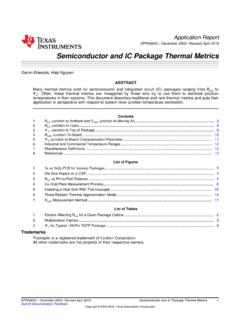
Transcription of Two transistor circuit replaces IC - hagtech.com
1 Two transistor circuit replaces IC Jim Hagerman, Hagerman Technology LLC, Honolulu, HI, I am always impressed with the way semiconductor manufacturers go out of their way to make the end designer s job easier. One example is the LTC4300 recently introduced by Linear Technology. This chip buffers I2C clock and data lines to/from a hot-swappable card. No easy task since it must work bi-directionally (both sides can be driven actively at the same time) without latching. However, as is sometimes the case, a complicated circuit can be replaced by a simple one without much loss of performance. The entire IC can be replaced by four transistors and two resistors. Schematic 1 shows the circuit for one signal only (either clock or data). Two NPN transistors wired head-to-tail form the heart of the circuit .
2 I2C signals are open collector (or drain) type so can only actively pull down. When ENABLE is high, a low going SCL signal drives the emitter of one of the transistors as a common base amplifier. The 10k resistor in the base provides enough current to saturate the collector and drop the Vce voltage to about , thereby pulling the other side low. It is like a very efficient diode. With ENABLE low, the hot swappable side has no affect on the signal, with or without power. Schematic 1. circuit of I2C hot-swappable level translator/buffer (clock side shown). The two- transistor circuit offers the additional benefit of acting as a level translator between two different logic levels. In this example, I show a buffer/translation between a system and a 5V card. For proper operation, the ENABLE line must not go higher than the lower of the two VCC.
3 The photos show actual operation at 100kHz. There are some edge glitches and overshoot on the signal (due to transistor junction capacitance), but should be acceptable for many low-cost applications. Photo 1. circuit driven by 5V side. Photo 2. circuit driven by side. [1] Two transistors form bi-directional level translator , Jim Hagerman, EDN 11/7/96 [2] Low-voltage interface circuits translate to 5V , CC Poon & Edward Cui, EDN 11/5/98