Transcription of ULTIMA #53-644 Programmable Digital Ignition …
1 ULTIMA #53- 644 programmable digital ignition system DESCRIPTIONThe ULTIMA Digital Ignition is designed to provide the correct curves and total timing for ULTIMA enginesand other larger cubic inch or highperformance engines. These units will also replace the OEM HD factory Ignition module and sensor used on 1983 and later Harley-DavidsonEVO motors. It is also an ideal upgrade for early electronic and breaker-point systems that require a mechanical advancer. The entire ignitionfits inside the engine in place of the cam sensor or point plate and connects directly to the coils without the use of an external unit will operate in single - or dual-fire mode and features 8 advance curves and 4 rpm limits to fit a broad range of engine builds andriding styles. For nitrous and turbo equipped bikes, a single stage retard is tach output is included, eliminating the need for an additional adapter when operating in single fire mode. Two diagnostic indicators assistin trouble shooting and static 53-644ignition module is preset to 3 dead-revolutions (no spark) to aid in easier starting & longer starter kickstart application, programming software will need to be purchased seperately.
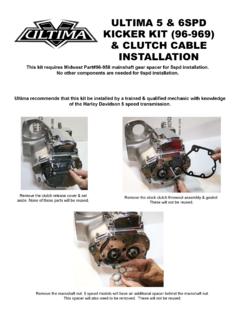
2 This allows the installer to remove the dead-revs. Theignition will then spark on the first compression/spark event. INSTALLATION NOTES**IMPORTANT**Coil primary resistance must be in the range of to ohms.**IMPORTANT** Carbon, graphite or spiral core type suppression spark plug wires are required to reduce interference. Do not use metal core wires.**IMPORTANT**This ULTIMA Ignition requires the gold colored timing rotor used on 1983 and later EVO motors (HD part no. 32402-83). The earlier silver colored cup will not work properly. Bikes originally equipped with points (except distributors) or early electronic Ignition will accept the later model cup without modification. DUALFIRE INSTALLATIONS ingle plug: use Dynatek DC6-1 or a coil with - ohms resistance. Dual plug: use two DC2-1 coils wired in series(equals 3 ohms).1. Remove the stock Ignition module. Remove the outer and inner covers on the cam position sensor. Mark the engine case near the middle ofthe sensor.
3 Remove the cam position sensor. The pins may be removed form the connector housing by slowly but firmly pulling the wires fromtherear of the connector. 2. Feed the wires of the Ignition through the hole in the engine case and seat the Ignition . Rotate until the timing pickup (nearest to theswitches) is at the mark made in step 1. Replace the screws that held the cam position sensor, finger Remove the wires from the coil. Use a test light or meter to find the white wire that has +12V when boththe key and the Run/Stop switchesare on (later models have only a single white/black wire). Attach this andthe white wire from the Ignition to one of the primary the pink wire from the Ignition to the other primary Tach connection (if equipped). Attach the pink wire from the tach to the Ignition green wire with the large (.250) blade connectors. If thebike had only one pink (or pink/black) wire at the coil, connect this to the Ignition green notconnect the Ignition tach wire to the coil or damage to the Ignition may the wire from the VOES (Vacuum Operated Electronic Switch).
4 Connect the Ignition purple wire with the small (.187) receptacleterminal. If the VOES is not installed, see the tuning tips on the last page. On allUltima Engines, we do not recommend the VOES blue wire is left unconnected. If there is no tach, the green wire is left unconnected. These should be folded back and tucked into theharness sleeve. The unused stock wire harness can be removed or taped Skip to the Configuring The Mode Switches section of these instructions. SINGLE FIRE INSTALLATION (Two coils, one firing each cylinder)Single plug: use Dynatek DC6-5 Twin-Fire II Performance Coil or two DC3-1 single output coils. Dual plug: use two DC1-1 coils or DC6-4 Twin-Fire. Mounting brackets for two-coil installations are available from your Follow the Dual Fire Installation Instructions above, through step Remove the coil. Use a test light or meter to find the white wire that has +12V when boththe key and the Run/Stop switches are on (somemodels have only a single white/black wire).
5 Attach this andthe white wire from the Ignition to the coil (+) terminal (a jumper is supplied fortwo-coil installations). Note: dual tower coils do not have a (+) terminal; either one can be 3. Connect the Ignition pink wire to the rearcylinder coil (-) terminal. The blue wire connects to the frontcylinder coil (-) Tach connection - attach the pink wire from the tach to the Ignition green wire with the large (.250) blade connectors. If there is no tach,fold the wire back into the harness the bike had only one pink (or pink/black) wire at the coil, connect this to the Ignition s green notconnect the ignitions tach wire to the coil or damage to the Ignition may the wire from the VOES (Vacuum Operated Electric Switch). Connect the Ignition purple wire with the small (.187) receptacleterminal. If the VOES is not installed, see the tuning tips on the last page. On all ULTIMA Engines, we do not recommend using the VOES there is no tach, the green wire can be folded back and tucked into the harness sleeve.
6 The unused stock wire harness can be removed totaped up. CONFIGURING THE MODE SWITCHESThis Ignition has 6 mode switches which allow you to configure the Ignition for your engine build and riding style. The switch position label islocated on the Ignition for future (NO VOES)- Follows preset curve shown in chart for specific engine configurations when VOES wire is not used - (low vacuum curves) DO NOT ground VOES wire for these curves. Use this setting for ULTIMA engines.(USING VOES)- Allows timing to reach full advance by 1500 rpm under light engine load conditions, improving throttle response and gas mileage when the VOES is present. Wide open throttle follows selected pre-set curve. (high vacuum curves)ONRetardUses the wire to retard timing for nitrous or turbo equipped bikes. See below for further 2 Switch 3 Advance CurveDescriptionOFFOFFC urve 1 -This curve brings up the advance the earliest and to the highest final value(most aggressive).
7 Used on 80 and 96Ci 2 -This curve brings up the advance a little slower than curve 1. Used on 100 and 3 -This curve is good for hi compression engines and ULTIMA 113, 120 and 127Ci, advance comes in slower than curve 2 and to a lower final 4 - This curve should only be used if your 120 or 127 Ci still detonates using curve 3 and on all 130 and 140 Ci engines. Advance is brought in still slower and to a lesser final value than curve 3 (least aggressive).The proper advance curve will be determined by the level of engine modification, weight of bike and rider, gasoline octane rating, airtemperature, altitude, etc. If you experience any pinging , use a less aggressive curve. Generally, you should run the curve that is mostaggressive without causing 4 Switch 5 Rev LimitApplicationOFFOFF5500 RPMAll ULTIMA enginesONOFF6000 RPMmodified ULTIMA enginesOFFON6500 RPM(most Harley valve trains don t like to be revved this high)ONON7000 RPMS witch 6 Firing ModeOFFDual FireONSingle Fire STATUS LED FUNCTIONThe red status LED is used for verifying system operation and setting timing.
8 When power is turned on, the LED should blink for 1/4 second. Ifthe pickup is near a firing point, the LED will blink, then stay on. This indicates the unit has passed its self the status LED flashes rapidly when the engine is not running, an over-current or short circuit fault is indicated. Check for proper coilresistance ( to ohms) and wiring. Correct the problem, then turn the Ignition off for one second, then back on to clear the the engine is cranked over, the LED will blink indicating the pickups are generating timing pulses. The pick up is designed such that the LEDwill come on at about 45 degrees before top dead center and go off at top dead center for each cylinder. This corresponds to the leading edgeof the window in the rotating cup (45 BTDC) and the trailing edge (TDC). STATIC TIMING THE MOTORR emove the timing inspection plug. With the bike in high gear turn the rear wheel to get the crankshaft to top dead center on the compressionstroke of the front cylinder (TDC mark aligned in the inspection hole).
9 Removing the spark plugs will make it easier to turn the the Ignition to cause the status LED to turn off and on. Carefullyfollowthis next instruction:find the point where the LED just turns offwhile rotating the base plate in a clockwisedirection. Lock down the Ignition . The initial timing is now set close to optimum. Final timing maybe checked and set dynamically to compensate for normal production tolerances in the timing rotor, camshaft indexing, flywheel marking, the Ignition has to be rotated an extreme amount or does not have enough adjustment to bring the timing in, the engine may be on itsexhaust stroke. Remove the Ignition and observe the timing rotor. The timing pickup (near the switches) should be sitting in one of thewindows with the Ignition installed . The shorter distance to the other window should be CLOCKWISE. If not, rotate the crankshaft 1revolution and check again. DYNAMIC TIMINGTo set the Ignition timing dynamically (with the engine running), use the following procedure:- Verify what advanced timing mark is on your HD - 35 ULTIMA 80 thru 113 Ci - 30 ULTIMA 120, 127, 130 and 140 Ci - 25 (all pre 2006 ULTIMA 120-127 Ci had 30 advance timing marks)- Select the curve that will produce the correct total timing for your engine configuration (see chart on last page) by changing switch 2 and 3 toproper Grounding the VOES wire will cause the Ignition to get total advance by 1500 rpm.
10 Connect a timing light to the front cylinder plug Rev the engine above 1500 rpm. The full advance mark should come into view. This will verify the Ignition is set properly. Now reset theDIP switches for the mode you want to - when the switch settings are changed, the power to the module must be turned off and back on for the new settings to take - Dial back timing lightsuse the mark for reference and timing is read off the light. On all bikes it is easier to reference the and advance timing marks to the alternator rotor so oil will not affect viewing the flywheel marks. VOES/RTD LED FUNCTIONThe green VOES/RTD LED lights when the violet wire is grounded. With the Ignition in normal mode and the VOES connected, the green LEDwill be on most of the time (engine vacuum present). In Retard Mode, the LED can be used to check operation of the retard controller. (SeeRETARDMODEUSING THE VOES WIRE below.) SWITCH (NOT RECOMMENDED ON ULTIMA ENGINES)VOES switches sense partial throttle openings (high vacuum) and open throttle (low vacuum) conditions in the intake manifold.