Transcription of UNDERSTANDING SUB-HARMONICS - ERLPhase
1 UNDERSTANDING SUB-HARMONICS Joe Perez, , ERLP hase Power Technologies, Winnipeg, MB, Canada Introduction Over the years, engineers have employed fundamental principles of electrical engineering to solve system problems. For example, series reactors are used to limit the amount of fault current since inductors resist a change in current. Similarly, series line capacitors are used to increase the amount of real power by cancelling a portion of the inductive reactance. However, some solutions can create new problems in the system, as is the case with series line compensated capacitors.
2 When a capacitor is used in a transmission line as a series element, sub-harmonic currents with frequencies below the fundamental are created. Extensive research and study have been done, and the consequences of sub-harmonic currents can be catastrophic. The effects of SUB-HARMONICS were visualized back in 1971 after a synchronous generator shaft failure [3]. Since then, generator manufacturers and utilities have worked together to identify problems between the interaction of series capacitors and generators. In recent months, a couple of incidents one in Texas and another in Minnesota have been identified where SUB-HARMONICS were implicated in creating an increased voltage and current oscillations.
3 One common factor in these two events is that they both involved wind generation. After decades of research, there are various phenomena that can be attributed to SUB-HARMONICS . SUB-HARMONICS can create induction generator effects, torsional interactions, torque amplification, sub-synchronous resonance, and transformer saturation. For the interaction between wind generation and series compensated lines, research that will help determine the real cause is still underway; however, the evidence records seem to point towards an induction generator effect phenomena. As a result, this paper provides focuses the induction generation effect, and gives a brief description of torsional interactions and torque amplifications.
4 Additionally, this paper provides simulations that help the reader to visualize the effect and offers a relay solution for SUB-HARMONICS . 2 SUB-HARMONICS It is well known that nonlinear loads will produce harmonics by drawing currents that are not necessarily sinusoidal. In effect, inductive loads will produce harmonics that are multiples of the fundamental ( , 120Hz, 180Hz, 240Hz, etc.) In a similar manner, when a circuit involving a resistor, capacitor and inductor is connected in series, voltages and currents with frequencies below the fundamental ( , 20Hz, 25Hz, 30Hz, etc.)
5 Will be created [2]. These are called sub-harmonic frequencies; they will be denoted fer. SUB-HARMONICS were first discussed by Butler and Concordia shown in reference [4]. Experimenting with series capacitors and transformers in series, they discovered a large, abnormal current flow that was low in frequency and had distorted the entire current waveform. In addition, the transformer secondary voltage was also distorted. Subsequent research was performed, and the researchers discovered that the system resistance played an important role in the magnitudes of these sub-harmonic currents.
6 It is now known that the sub-harmonic frequencies in an RLC circuit will be damped out through the resistance of the circuit and will coexist in the system without presenting major problems [5]. However, during faults or switching events, the sub-harmonic currents are amplified and excited so that the resistance of the circuit can reach a point that is not enough to damp the sub-harmonic frequencies [6]. As a result, these frequencies can cause voltage and current amplification, as explained by the induction generator effect. Induction Generator Effect When a series capacitor is used to cancel a portion of the system reactance, the system will always end up with a natural frequency which is less than the system frequency and is referred to as the sub-harmonic [2].
7 This sub-harmonic frequency is defined by as: " 1 The generator armature sub-harmonic currents produce magnetic fields with frequency fer which are induced in the generator rotor. As a result, the induce currents in the rotor produces a rotor frequency defined as: 2 In consequence, this new added rotor frequency will result in sub-synchronous armature voltages which may enhance the sub-synchronous currents and may cause generator self excitation [1]. 3 Because the rotor is turning faster than the sub-harmonic armature currents with frequency fer, a slip is created simulating an induction machine and the slip is defined by s: 3 As we can see from equation 3, the slip will always be negative, which will result in a negative rotor resistance R as described in Figure 1.
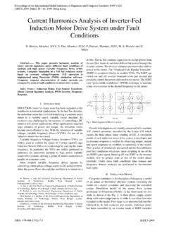
8 R =Rr/sXrXmRsXsI Figure 1: Induction generator effect circuit. The rotor resistance is defined as: 4 Since the slip (s) will always be negative, the damping effect of R will always be negative. If the series compensation is very high, the slip (s) will be very small and therefore R will be a negative large number [6]. If the addition of the damping resistance R and the resistance of the system is negative, voltage and current growing oscillations may build up to very dangerous high values. In order to emphasize this concept better, let take a look at the following example.
9 Figure 2 shows a series compensation circuit through a couple 525kV transmission line given by reference [7]. + + + IN ON 100 MVA Figure 2: Series Compensation Circuit 4 Using equation 1 we can find the natural frequency of this circuit as follows: " 60 36"# Using equation 3 we can calculate the slip: 36 6036 Using equation 4 we can calculate the damping with a rotor resistance of : The total resistance of the network of line, transformer and load is: Rnetwork = The total effective resistance is.
10 Reff = R + Rnetwork Rnet = + Rnet = 5 Since the net resistance is negative for this series compensated circuit, we can expect increasing sub-harmonic oscillation. Power System Model The simulations in Figure 2 below show the impact of the induction generator effects for the system. Figure 2: Three phase series compensated system. Figure 2 shows a three phase series compensated line composed of six 350 MVA generators, a to 735kV step-up transformer, two 300 km 735kV transmission lines, and two capacitors for 40% line compensation [8]. Case 1: System Response to SUB-HARMONICS with Line to Ground Fault.