Transcription of Understanding the Alternator - Autoshop 101
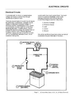
1 Kevin Sullivan, all rights reserved. the AlternatorTHIS AUTOMOTIVE SERIESON ALTERNATORS HASBEEN DEVELOPED BYKEVIN R. SULLIVANPROFESSOR OFAUTOMOTIVE TECHNOLOGYAT SKYLINE COLLEGESAN BRUNO, CALIFORNIAALL RIGHTS Sullivan, all rights reserved. the Alternator The charging system has threemajor components. TheBattery, Alternator , and theRegulator. This Alternator works togetherwith the battery to supply powerwhen the vehicle is running. The output of an Alternator isdirect current, however ACvoltage is actually created andthen converted to DC as voltageleaves the Alternator on its wayto the battery and the SystemKevin Sullivan, all rights reserved. the Alternator Four wires connect the Alternator to the rest of the charging system.
2 B is the Alternator output wire that supplies current to the battery. IG is the ignition input that turns on the Alternator /regulator assembly. S is used by the regulator to monitor charging voltage at the battery. L is the wire the regulator uses to ground the charge warning System CircuitKevin Sullivan, all rights reserved. the AlternatorAlternator Terminal Identification B TerminalAlternator OutputTerminal to Battery L TerminalGrounds Warning Lamp S TerminalSenses BatteryVoltage F TerminalRegulator BypassFull Field Testing IG TerminalIgnition Switch SignalTurns Regulator ONKevin Sullivan, all rights reserved. the AlternatorAlternator B+Output TerminalRegulator, Diode,& Brush CoverEnd Frame CoverDrive Frame CoverDrive PulleyMounting EarCirculation VentIdentificationLabelAlternator AssemblyKevin Sullivan, all rights reserved.
3 The Alternator The Alternator contains: A rotating field winding calledthe rotor. A stationary induction windingcalled the stator. A diode assembly called therectifier bridge. A control device called thevoltage regulator. Two internal fans to promote Sullivan, all rights reserved. the Alternator Most regulators are on the insidethe Alternator . Older models haveexternally mounted regulators. Unlike other manufacturers, thismodel can be easily serviced fromthe rear on the unit. The rear cover can be removed toexpose internal parts. However, today s practice is tocorrectly diagnose the problemand replace the Alternator as aunit, should one of it s internalcomponents DesignKevin Sullivan, all rights reserved. the Alternator Alternator drive pulleys eitherbolt on or are pressed on therotor shaft.
4 Both V and Multi-grove typesare used. Note this Alternator does nothave an external fan as part ofthe pulley assembly. While many manufacturers douse a external fan for Alternator has two internalfans to draw air in for PulleyKevin Sullivan, all rights reserved. the Alternator Removal of the rear coverreveals:BrushesDiode Rectifier BridgeRegulatorInside the AlternatorThe Rectifier Bridge convertsAC voltage to DC Brushes conduct currentto the rotor field Regulator controls thealternator Rings (part of the Rotor Assembly)Kevin Sullivan, all rights reserved. the Alternator Two slip rings are located on oneend of the rotor assembly. Eachend of the rotor field winding isattached to a slip ring. Thereby,allowing current to flow throughthe field winding.
5 Two stationary carbon brushesride on two rotating slip are either soldered orboltedBrushesKevin Sullivan, all rights reserved. the Alternator The regulator is the brain of thecharging system. It monitors both battery andstator voltages and dependingon the measured voltages, theregulator will adjust the amountof rotor field current to controlalternator output. Regulators can be mountedboth internal or technology uses aninternal RegulatorKevin Sullivan, all rights reserved. the Alternator The Diode Rectifier Bridge isresponsible for for theconversion or rectification of ACvoltage to DC voltage. Six or eight diodes are used torectify the AC stator voltage toDC voltage. Half of these diodes are use onthe positive side and the otherhalf are on the negative side.
6 Further details about therectifier bridge will be RectifierKevin Sullivan, all rights reserved. the AlternatorInside the AlternatorStator WindingRotor WindingAssembly Separating the case reveals:The stator winding developsvoltage and current beginsto flow from the inducedmagnetic field of the rotor winding assemblyrotates inside the statorwinding. The rotor generatesa magnetic Sullivan, all rights reserved. the AlternatorSlip RingsBearingInternal Cooling FanRotor AssemblyFinger PolesRotor Field WindingRotor ShaftInternalCooling FanKevin Sullivan, all rights reserved. the Alternator A basic rotor consists of a ironcore, coil winding, two slip rings,and two claw-shaped finger polepieces. Some models include supportbearings and one or two internalcooling fans.
7 The rotor is driven or rotatedinside the Alternator by anengine ( Alternator ) drive AssemblyKevin Sullivan, all rights reserved. the Alternator The rotor contains the fieldwinding wound over an ironcore which is part of the shaft. Surrounding the field coil aretwo claw-type finger poles. Each end of the rotor fieldwinding is attached to a slipring. Stationary brushesconnect the Alternator to therotor. The rotor assembly is supportedby bearings. One on the shaftthe other in the drive AssemblyKevin Sullivan, all rights reserved. the Alternator The rotor field winding createsthe magnetic field that inducesvoltage into the stator. The magnetic field is saturatesthe iron finger poles. One fingerpole become a north pole andthe other a south pole.
8 The rotor spins creating analternating magnetic field,North, South, North, South, FieldSouth FieldNorth FieldAlternatingMagnetic FieldKevin Sullivan, all rights reserved. the AlternatorStator WindingLaminated IronFrameStatorLead EndsThree PhaseWindingsNeutralJunctionKevin Sullivan, all rights reserved. the Alternator As the rotor assembly rotateswithin the stator winding. The alternating magnetic fieldfrom the spinning rotor inducesan alternating voltage into thestator winding. The strength of the magneticfield and the speed of the rotoraffect the amount of voltageinduced into the / StatorRelationshipKevin Sullivan, all rights reserved. the Alternator The stator is made with three setsof windings. Each winding is placed is adifferent position compared withthe others.
9 A laminated iron frameconcentrates the magnetic field. Stator lead ends that output tothe diode rectifier IronFrameStator Lead EndsStator WindingsThree WindingsNeutral Junction in the Wye design canbe identified by the 6 strands of wireKevin Sullivan, all rights reserved. the Alternator The stator winding has threesets of windings. Each is formedinto a number of evenly spacedcoils around the stator core. The result is three overlappingsingle phase AC sine wavecurrent signatures, A, B, C. Adding these waves togethermake up the total AC output ofthe stator. This is called threephase current. Three phase current provides amore even current Phase WindingsKevin Sullivan, all rights reserved. the AlternatorStator DesignTwo designs of stator windingare used.
10 Delta and style has four stator leads. Oneof the leads is called the NeutralJunction. The Neutral Junction iscommon to all the other wound stators can be identifiedby having only three stator leads, andeach lead will have the same numberof wires Sullivan, all rights reserved. the AlternatorWye DesignWye wound stators have threewindings with a common neutraljunction. They can be identifiedbecause they have 4 stator wound stators are used inalternators that require high voltageoutput a low Alternator windings are in series at anyone time during charge Sullivan, all rights reserved. the AlternatorDelta DesignDelta wound stators can beidentified because they have onlythree stator lead stators allow for highercurrent flow being delivered at windings are in parallel ratherthan series as like the Wye Sullivan, all rights reserved.