Transcription of UNRESTRAINED BEAM DESIGN – I
1 UNRESTRAINED beam DESIGN -I. UNRESTRAINED beam DESIGN I. 11. INTRODUCTION. Generally, a beam resists transverse loads by bending action. In a typical building frame, main beams are employed to span between adjacent columns; secondary beams when used transmit the floor loading on to the main beams. In general, it is necessary to consider only the bending effects in such cases, any torsional loading effects being relatively insignificant. The main forms of response to uni-axial bending of beams are listed in Table 1. Under increasing transverse loads, beams of category 1 [Table1] would attain their full plastic moment capacity. This type of behaviour has been covered in an earlier chapter. Two important assumptions have been made therein to achieve this ideal beam behaviour. They are: The compression flange of the beam is restrained from moving laterally, and Any form of local buckling is prevented. If the laterally UNRESTRAINED length of the compression flange of the beam is relatively long as in category 2 of Table 1, then a phenomenon, known as lateral buckling or lateral torsional buckling of the beam may take place.
2 The beam would fail well before it could attain its full moment capacity. This phenomenon has a close similarity to the Euler buckling of columns, triggering collapse before attaining its squash load (full compressive yield load). lateral buckling of beams has to be accounted for at all stages of construction, to eliminate the possibility of premature collapse of the structure or component. For example, in the construction of steel-concrete composite buildings, steel beams are designed to attain their full moment capacity based on the assumption that the flooring would provide the necessary lateral restraint to the beams. However, during the erection stage of the structure, beams may not receive as much lateral support from the floors as they get after the concrete hardens. Hence, at this stage, they are prone to lateral buckling , which has to be consciously prevented. Beams of category 3 and 4 given in Table 1 fail by local buckling , which should be prevented by adequate DESIGN measures, in order to achieve their capacities.
3 The method of accounting for the effects of local buckling on bending strength was discussed in an earlier chapter. In this chapter, the conceptual behaviour of laterally UNRESTRAINED beams is described in detail. Various factors that influence the lateral buckling behaviour of a beam are explained. The DESIGN procedure for laterally UNRESTRAINED beams is also included. Copyright reserved Version II 11-1. UNRESTRAINED beam DESIGN -I. Table 1 Main failure modes of hot-rolled beams Category Mode Comments 1 Excessive bending W This is the basic failure mode triggering collapse provided (1) the beam is prevented from buckling laterally,(2) the component elements are at least compact, so that they do not buckle locally. Such stocky beams will collapse by plastic hinge formation. 2 lateral torsional Failure occurs by a combination of W. buckling of long lateral deflection and twist. The beams which are proportions of the beam , support not suitably braced conditions and the way the load is in the lateral applied are all factors, which affect direction.
4 ( un failure by lateral torsional buckling . restrained beams). 3 Failure by local Unlikely for hot rolled sections, buckling of a which are generally stocky. Box section flange in Fabricated box sections may compression or require flange stiffening to prevent web due to shear premature collapse. or web under Web stiffening may be required for compression due Plate girder in shear plate girders to prevent shear to concentrated W buckling . loads Load bearing stiffeners are sometimes needed under point loads to resist web buckling . 4 Local failure by W Shear yield can only occur in very (1) shear yield of short spans and suitable web web (2) local stiffeners will have to be designed. crushing of web (3) buckling of Shear yield Local crushing is possible when thin flanges. concentrated loads act on unstiffened thin webs. Suitable stiffeners can be designed. Crushing of web This is a problem only when very wide flanges are employed.
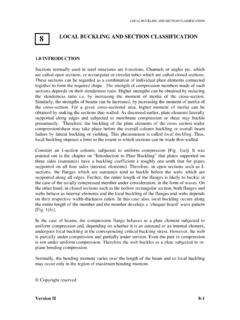
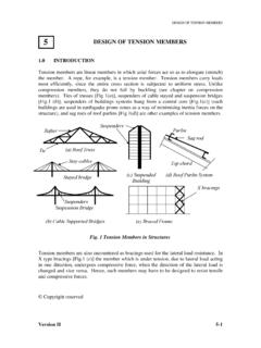
5 Welding of additional flange plates buckling of thin flanges will reduce the plate b / t ratio and thus flange buckling failure can be avoided. Version II 11-2. UNRESTRAINED beam DESIGN -I. SIMILARITY OF COLUMN buckling AND lateral buckling . OF BEAMS. It is well known that slender members under compression are prone to instability. When slender structural elements are loaded in their strong planes, they have a tendency to fail by buckling in their weaker planes. Both axially loaded columns and transversely loaded beams exhibit closely similar failure characteristics due to buckling . Column buckling has been dealt with in detail in an earlier chapter. In this section, lateral buckling of beams is described and its close similarity to column buckling is brought out. Consider a simply supported and laterally unsupported (except at ends) beam of short- span subjected to incremental transverse load at its mid section as shown in (a).
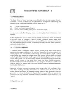
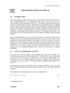
6 The beam will deflect downwards in the direction of the load [Fig. 1(b)]. W W. Undeflected position Deflected position . (a) (b). Fig. 1(a) Short span beam , (b) Vertical deflection of the beam . The direction of the load and the direction of movement of the beam are the same. This is similar to a short column under axial compression. On the other hand, a long-span . beam [ (a)], when incrementally loaded will first deflect downwards, and when the load exceeds a particular value, it will tilt sideways due to instability of the compression flange and rotate about the longitudinal axis [Fig. 2(b)]. Horizontal W . Twisting W W movement Vertical movement . Before After (a) buckling buckling (b). Fig. 2(a) Long span beam , (b) Laterally deflected shape of the beam Version II 11-3. UNRESTRAINED beam DESIGN -I. The three positions of the beam cross-section shown in Fig. 2(b) illustrate the displacement and rotation that take place as the midsection of the beam undergoes lateral torsional buckling .
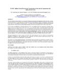
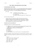
7 The characteristic feature of lateral buckling is that the entire cross section rotates as a rigid disc without any cross sectional distortion. This behaviour is very similar to an axially compressed long column, which after initial shortening in the axial direction, deflects laterally when it buckles. The similarity between column buckling and beam buckling is shown in Fig. 3. P. Y. M. X B. B. Z. B. M B.. P. Column buckling u EA EI y beam buckling u >.. 3 Section B-B EIx >EIy EIx >GJ Section B-B. Fig. 3 Similarity of column buckling and beam buckling In the case of axially loaded columns, the deflection takes place sideways and the column buckles in a pure flexural mode. A beam , under transverse loads, has a part of its cross section in compression and the other in tension. The part under compression becomes unstable while the tensile stresses elsewhere tend to stabilize the beam and keep it straight. Thus, beams when loaded exactly in the plane of the web, at a particular load, will fail suddenly by deflecting sideways and then twisting about its longitudinal axis [ ].
8 This form of instability is more complex (compared to column instability) since the lateral buckling problem is 3-dimensional in nature. It involves coupled lateral deflection and twist , when the beam deflects laterally, the applied moment exerts a torque about the deflected longitudinal axis, which causes the beam to twist. The bending moment at which a beam fails by lateral buckling when subjected to a uniform end moment is called its elastic critical moment (Mcr). In the case of lateral buckling of beams, the elastic buckling load provides a close upper limit to the load carrying capacity of the beam . It is clear that lateral instability is possible only if the following two conditions are satisfied. The section possesses different stiffness in the two principal planes, and The applied loading induces bending in the stiffer plane (about the major axis). Similar to the columns, the lateral buckling of UNRESTRAINED beams, is also a function of its slenderness.
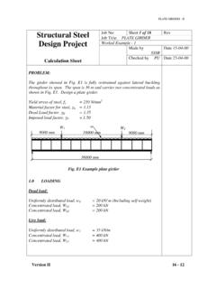
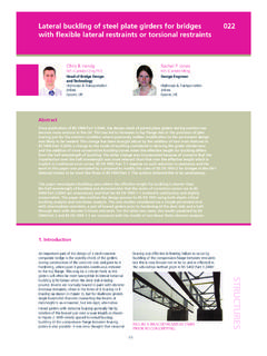
9 Version II 11-4. UNRESTRAINED beam DESIGN -I. INFLUENCE OF CROSS SECTIONAL SHAPE ON lateral . torsional buckling . Structural sections are generally made up of either open or closed sections. Examples of open and closed sections are shown in Fig. 4. Wide Flange beam Standard beam Channel Angle Tee Open sections Tubular Box Closed sections Fig. 4 Open and closed sections Cross sections, employed for columns and beams (I and channel), are usually open sections in which material is distributed in the flanges, away from their centroids, to improve their resistance to in-plane bending stresses. Open sections are also convenient to connect beams to adjacent members. In the ideal case, where the beams are restrained laterally, their bending strength about the major axis forms the principal DESIGN consideration. Though they possess high major axis bending strength, they are relatively weak in their minor axis bending and twisting.
10 The use of open sections implies the acceptance of low torsional resistance inherent in them. No doubt, the high bending stiffness (EIx) available in the vertical plane would result in low deflection under vertical loads. However, if the beam is loaded laterally, the deflections (which are governed by the lower EIy rather than the higher EIx) will be very much higher. From a conceptual point of view, the beam has to be regarded as an element having an enhanced tendency to fall over on its weak axis. In contrast, closed sections such as tubes, boxes and solid shafts have high torsional stiffness, often as high as 100 times that of an open section. The hollow circular tube is the most efficient shape for torsional resistance, but is rarely employed as a beam element on account of the difficulties encountered in connecting it to the other members and Version II 11-5. UNRESTRAINED beam DESIGN -I. lesser efficiency as a flexural member.