Transcription of User Manual English - APC UPS, APC Battery …
1 990-850003/2007 APC Smart-UPS 5000 VA 208/230 VacTower/Rack-Mount 5 UUninterruptible power SupplyUser ManualEnglishSmart-UPS 5000 VA 208/230 Vac Tower/Rack-Mount 5U user ManualiContentsIntroduction.. 1 About this UPS .. 1 Unpack .. 1 Specifications .. 2 Installation.. 2 Rack-mount configuration .. 2 Rack-mount to tower conversion procedure .. 4 Input hardwire 230 V models only .. 5 Accessories .. 5 Connect batteries .. 6 Configure bezel .. 6 Connect display cable and install bezel .. 7 Start-up .. 8 Connect Equipment and power to the UPS .. 8 Communication Ports .. 9 Emergency power Off .. 9 Operation.. 10 Display Panels .. 10 Display Panel Indicators and Function Buttons .. 10 Configuration .. 12 UPS settings .. 12 Troubleshooting .. 14 Maintenance, Transport, and Service .. 17 Replace Battery modules.
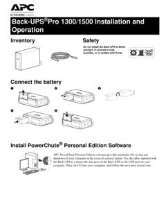
2 17 Service .. 18 Two-Year Warranty .. 19 Regulatory Information .. 20 Smart-UPS 5000 VA 208/230 Vac Tower/Rack-Mount 5U user Manual1 IntroductionAbout this UPSThe American power Conversion (APC ) uninterruptible power supply (UPS) provides protection for electronic equipment from utility power blackouts, brownouts, sags and surges. The UPS filters small utility line fluctuations and isolates electronic equipment from large disturbances by internally disconnecting from utility line power . The UPS provides continuous power from the internal Battery until utility power returns to safe levels or the Battery is fully the Safety Guide before installing the the UPS upon receipt. Notify the carrier and dealer if there is packaging is recyclable; save it for reuse or dispose of it UPS and the Battery modules are heavy.
3 Remove the Battery modules to lighten the UPS during installation. Refer to Battery removal instructions on the the package contents: UPS Front bezel Display bezel Top covers (2) and one screw (tower configuration) EPO connector Serial cable Eight ornamental screws for securing the unit in the rack Four cage nuts Two rack-mount brackets (used as stabilizers in tower configuration) Eight pan-head locking screws Two rail cleats Eight pan-head screws Literature kit containing: Product documentation Smart-UPS user Manuals CD PowerChute Business Edition CD Safety information Warranty informationAdditional contents for 230 V models: IEC power connector IEC jumper cables8882241 Hardwarepan head screws for securing rail cleats to UPSpan head locking screws for securing rack-mount brackets/stabilizer brackets to the UPSpan head locking screw (black) for securing top covers to UPSornamental screws for securing UPS to rackcage nuts for rack installationrack-mount brackets for rack-mount configurationstabilizer brackets for tower configurationrail cleats2 Smart-UPS 5000 VA 208/230 Vac Tower/Rack-Mount 5U user ManualSpecificationsNOTE: The model and serial numbers are located on a small, rear panel label.
4 For some models, an additional label is located on the chassis under the front configurationThis unit is intended for mounting in a four post rack. To order a two post rack-mount kit contact your dealer or refer to the APC Web site, UPS and the Battery modules are heavy. Remove the Battery modules to lighten the UPS during installation. Refer to the Battery removal instructions on the rack-mount brackets and rail cleatsFour screws must be used to secure each rail bracket and rail cleat to the UPS. One rack-mount bracket and one rail cleat must be secured to the both sides of the to 104 F (0 to 40 C)5 to 86 F (-15 to 30 C) charge the UPS Battery every six months86 to 113 F (30 to 45 C) charge the UPS Battery every three monthsThis unit is intended for indoor use only. Select a location sturdy enough to handle the not operate the UPS where there is excessive dust or the temperature or humidity are outside the specified factors impact Battery life.
5 High temperatures, poor utility power , and frequent, short duration discharges will shorten Battery ElevationOperatingStorage6562 ft (2,000 m)50,000 ft (15,240 m)Humidity0 to 95% relative humidity, non-condensingWeight215 lbs (98 kg) with Battery module107 lbs (49 kg) without Battery module27 lbs (12 kg) each Battery module215 lbs (98 kg) 4x4xRack-mount bracketfour post rack-mount positionRail cleatSmart-UPS 5000 VA 208/230 Vac Tower/Rack-Mount 5U user Manual3 Install unit in rackEnsure rack stability prior to installing devices in the UPS should be installed at or near the bottom of the spacersWhen installing rails in the rack, install two cage nuts above each rail, (see diagram).Secure the UPS in the rack using the four cage nuts and eight ornamental screws included in the batteriesSecond cage nut: count three holes up from first cage nutFirst cage nut: count four holes up from top edge of railConnect only the first two batteries in the string of three batteries.
6 Be sure that the Battery connectors are fully not connect the single Battery or the last Battery installed in the string of three and secure Battery doors4x3 holes4 holes3 holes4 holes4 Smart-UPS 5000 VA 208/230 Vac Tower/Rack-Mount 5U user ManualRack-mount to tower conversion procedureThe UPS and the Battery modules are heavy. Remove the Battery modules to lighten the UPS during installation. Refer to the Battery removal instructions on the stabilizer bracketsStand the UPS on the side with the embossed a stabilizer bracket (supplied), to both sides of the each bracket with two pan head locking screws (supplied).Install two top coversInstall the large top cover by placing it in the slots on the UPS and sliding the cover forward. Install the small top cover by placing it in the slots on the UPS and sliding the cover the top covers with a #8 black screw (supplied).
7 4x2x2xClose and secure the Battery doorsFoam spacersInstall batteriesConnect only the first two batteries in the string of three batteries. Be sure that the Battery connectors are fully not connect the single Battery or the last Battery installed in the string of three 5000 VA 208/230 Vac Tower/Rack-Mount 5U user Manual5 Input hardwire 230 V models onlyHardwiring must be performed by a qualified electrician. Adhere to all national and local Use a dedicated branch circuit with a maximum of 32 A of over-current protection, (either a circuit breaker of fuses).A lower rated branch may be used depending on the requirements of the UPS an additional 600 W for the UPS during the Battery replacement Switch the circuit breaker OFF prior to connecting equipment and power to the Remove the access panels located on the rear panel of the Remove the knockout from the input access Use # 10 AWG (5 mm ).
8 Strip approximately six inches ( mm) of the outer jacket from the input cable exposing the .5 inch ( mm) of the individual wire Route the input cable through the hole in the input access panel. Apply an appropriate strain Connect the ground wire prior to connecting the line Replace the access panels and secure each panel with three accessories prior to connecting power to the to the APC Web site, for available accessories. Input/output hardwire kit Two post rack optionL1 L2/NAccess panel screwsTerminal blockaccess panelinputaccess panel6 Smart-UPS 5000 VA 208/230 Vac Tower/Rack-Mount 5U user ManualConnect batteries Configure bezelSnap the display out of the bezel. Rotate the bezel and reinstall the display for a tower all of the batteries have been connected, tuck the Battery cables and the Battery disconnect cord in the space provided in the Battery doors.
9 This will ensure a secure fit of the bezel to the disconnect cordRack-mount configurationTower configurationBattery disconnect cordDisplaySmart-UPS 5000 VA 208/230 Vac Tower/Rack-Mount 5U user Manual7 Connect display cable and install bezelRack-mount configurationTower configurationDisplay cableDisplay cable8 Smart-UPS 5000 VA 208/230 Vac Tower/Rack-Mount 5U user ManualStart-upConnect Equipment and power to the UPS1. The UPS features a chassis ground connection screw located on the rear panel, for connecting the ground leads on transient voltage to connecting the grounding wire, ensure that the UPS is NOT connected to utility or Battery Connect equipment to the V models: Plug the UPS into a two-pole, three-wire, grounded receptacle only. Avoid using extension V models: Refer to the Input Hardwire section in this To use the UPS as a master on/off switch be sure all connected equipment is switched PanelsStart the UPS1.
10 Press the button on the front panel to start the UPS. The Battery charges to 90% capacity during the first four hours of normal operation. Do not expect full Battery run capability during this initial charge period. Refer to the APC Web site, for Battery For optimal computer system security, install PowerChute Smart-UPS monitoring V models230 V modelsSmart-UPS 5000 VA 208/230 Vac Tower/Rack-Mount 5U user Manual9 Communication PortsEmergency power OffThe emergency power off (EPO) feature is user configurable. EPO provides immediate de-energizing of connected equipment from a remote location, without switching to Battery Use the EPO connector supplied with the Use a normally-open contact to connect the +24 terminal to the IN terminal. External voltage is not Wire the four-pin connector to the EPO EPO interface is a Safety Extra Low Voltage (SELV) circuit.