Transcription of User's Guide schematics UG233: USB Type-C Reference …
1 ug233 : USB Type-C Reference DesignUser's GuideThe EFM8 USB Type-C Reference design is intended to aid thedevelopment of various USB Type-C applications and consists ofa development board, Simplicity Studio libraries, and board contains Power Delivery (PD) controllers, Billboard devices, and AlternateMode POINTS Describes the Type-C Reference designboard Explains how to load the softwareexamples and begin evaluation anddevelopment Discusses the power scenarios/optionsrelated to the Reference board Shows how to configure the Debug SerialTerminal Shows the Reference design | Smart. Connected. 1. introduction and Running the DemoThe USB Type-C Reference design is intended to aid the development of various USB Type-C applications and consists of a develop-ment board, Simplicity Studio libraries, and example code.
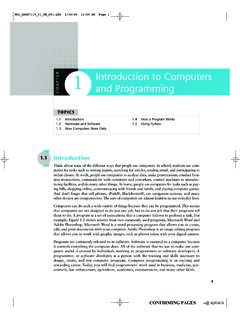
2 Out of the box, the board is configured as a DisplayPort alternate modevideo adapter. For a quick demo, simply plug the USB Type-C captive cable into a compatible host and a monitor cable into the miniDisplayPort (mDP) receptacle. In the absence of a DisplayPort-capable monitor a video converter dongle, like the white VGA-to-mDPshown in the image, can be used. However, in this case, J22 must be closed in order to power the external Demo SetupUG233: USB Type-C Reference design User's GuideIntroduction and Running the | Smart. Connected. | 12. Board DescriptionThe Type-C Reference design board is a platform for developing and evaluating hub and dongle Type-C solutions. The board containsPower Delivery (PD) controllers, Billboard devices, and Alternate Mode functionality.
3 The PD Controller is implemented with EFM8 BusyBee 3 (EFM8BB3) MCU, and takes advantage of the feature-rich peripherals available on-chip. The only necessary external circuits arethe CC lines voltage clamps for Dead-Battery, the slew rate control capacitors, and a Pull-Up (Rp) switch for Power Role SWAP func-tion and DRP support. The board also contains a Billboard device implemented with the EFM8 Universal Bee 1 (EFM8UB1) MCU andallows for Alternate Mode to be used and sent through the Type-C port. For debugging and communication purposes, a USB-to-QuadUART Bridge Controller (CP2108) is used to print debug messages from all MCUs to a USB host serial terminal. Most of the availableGPIOs from each MCU are routed to pin headers for convenient interfacing with instrumentation and/or system-level integration.
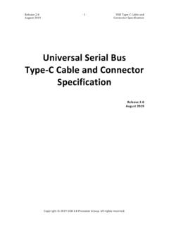
4 TheC2 debug interface for each MCU is also routed to headers so that individual firmware can be loaded onto each : USB Type-C Reference design User's GuideBoard | Smart. Connected. | 2 Figure Board LayoutTable Board Component MapComponentNameFunctionJ26 JumperMust be closed for proper Mode PD controller MCU power supply monitoring jumper. Must beclosed for normal device MCU power supply monitoring jumper. Must be closed for nor-mal Type-C DisplayPort Alternate Mode Power Delivery programming interface connector for U3 Billboard class programming interface connector for U1 Type-C charging port Power Delivery programming interface connector for U6 SocketMini DisplayPort USBUsed for printing debug messages to a serial Type-C ReceptacleCharging port connector.
5 The socket is rated 3A push button switch for U3 push button switch for U1 push button switch for U6 headerI2C : USB Type-C Reference design User's GuideBoard | Smart. Connected. | 3 The following block diagram can be used to understand the main functions of the Reference design and the connections between devi-ces and Functional Block Diagram OverviewUG233: USB Type-C Reference design User's GuideBoard | Smart. Connected. | 43. Evaluation and DevelopmentThe Type-C Reference design with all of the above-mentioned capabilities is available for free once a Software License Agreement hasbeen signed. After getting the demo to run, the next step is to load the software examples and source code to begin and extract the Release folder from the provided Reference Reference design and install Simplicity Studio from the Simplicity Studio IDE and switch workspaces using the [File] [Switch Workspace].
6 Locate the release folder that wasextracted in step one and select the top-level folder as the the project by going to [File] [Import] [Simplicity Studio] [MCU Project]. the SLS directory under the Reference design folder and select one of the projects to develop: ufp_dongle, knlexample, that EFM8BB31F64G part is selected and click [Next]. project is now imported and can build, run, or be altered to fit specific UFP Dongle development assistance and information on the programming interface please open [ ] in the [doc] of the UC3 headers on the board connects the C2 interface of a specific device. The color-coded circles in the Figure BoardLayout on page 3 show which header connects to which device. By using a debug adapter like this , the firmware developed in Simplicity Studio can be loaded onto the : USB Type-C Reference design User's GuideEvaluation and | Smart.
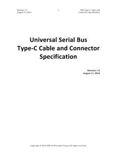
7 Connected. | 54. PowerFor developers convenience, the Reference board supports a flexible powering scheme, as depicted in the following diagram:Figure Power Block DiagramVarious power sources can co-exist due to the presence of separate diodes. Below are some power provides power from the USB-C host (DFP). No other power sources are needed for the functional : If a VGA to mDP dongle is used, VCONN alone may not be able to supply enough debug adapter provides power while flashing/debugging the MCU in Simplicity board can be powered from the USB host which runs the Serial Terminal 9 V wall V voltage can be obtained from an external LDO (Max. 500 mA), or from the EFM8UB1 internal LDO (Max. 100 mA). Thefollowing jumper settings are for evaluating different 5 V LDO and EFM8UB1 powered from 5 V: J3 short, J12 short, J19 open, J18 5 V LDO and EFM8UB1 powered from V: J3 short, J12 open, J19 short, J18 5 V internal LDO: J3 open, J12 short, J19 open, J18 shortUG233: USB Type-C Reference design User's | Smart.
8 Connected. | 65. Debug Serial Terminal the appropriate CP2108 (USB to Quad UART Bridge Controller) driver for your connecting the development board for the first time, it may take a while until the USB host enumerates the device. Check thedriver installation message and/or the Device Manager for Bridge Driver a Serial Terminal Application (Ex: Realterm). the successful USB device enumeration, open the terminal window and connect to the desired port with the following settings:Figure Debug ConnectionUG233: USB Type-C Reference design User's GuideDebug Serial Terminal | Smart. Connected. | 76. SchematicsThe schematics for the Reference design board are shown below. These are also available within the Reference design Alternate Mode UFPUG233: USB Type-C Reference design User's | Smart.
9 Connected. | 8 Figure USB Type-C Charging PortUG233: USB Type-C Reference design User's | Smart. Connected. | 9 Figure Billboard DeviceUG233: USB Type-C Reference design User's | Smart. Connected. | 10 Figure USB to UART BridgeUG233: USB Type-C Reference design User's | Smart. Connected. | 11 Laboratories West Cesar ChavezAustin, TX 78701 USAS implicity StudioOne-click access to MCU and wireless tools, documentation, software, source code libraries & more. Available for Windows, Mac and Linux!IoT and Laboratories intends to provide customers with the latest, accurate, and in-depth documentation of all peripherals and modules available for system and software implementers using or intending to use the Silicon Laboratories products.
10 Characterization data, available modules and peripherals, memory sizes and memory addresses refer to each specific device, and "Typical" parameters provided can and do vary in different applications. Application examples described herein are for illustrative purposes only. Silicon Laboratories reserves the right to make changes without further notice and limitation to product information, specifications, and descriptions herein, and does not give warranties as to the accuracy or completeness of the included information. Silicon Laboratories shall have no liability for the consequences of use of the information supplied herein. This document does not imply or express copyright licenses granted hereunder to design or fabricate any integrated circuits.