Transcription of AN1953 - Microchip Technology
1 2015 Microchip Technology 1 INTRODUCTIONThe USB-IF has secured the ubiquitous nature of USB for years to come with the radically updated usb type -C con-nector. While the sleek new reversible form factor has been significant for generating buzz and excitement from the gen-eral consumer market, the significantly expanded feature-set is what will eventually transform the desktop and entertainment usb type -C cable is now poised to become the universal cable, as it is capable of supplying blazing fast data transfer speeds of up to 10Gb/s, 100W of continuous power flow, and ultra high bandwidth video capabilities made avail-able through Alternate Modes all in parallel with a single document is intended for those already familiar with who are interested in the high level details of the expanded feature set that the usb type -C cable brings to , General InformationSection , usb type -C CablesSection.
2 CC PinsSection , VCONN SupplySection , USB Power Delivery , Alternate ModesREFERENCESThis document is an introduction to usb type -C and is not intended to be a replacement to the official specification. Consult the following specifications for technical details not described in this document. usb type -C Specification USB Power Delivery Specification USB Specification USB Specification USB Specification USB Battery Charging to usb type -C Author:Andrew Rogers Microchip Technology 2 2015 Microchip Technology INFORMATIONThe usb type -C cable is a reversible 24-pin interconnect created by the USB-IF. The usb type -C specification was first released in August usb type -C cable is a universal cable that addresses the needs for a wide range of computing, display, and charging applications.
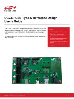
3 The long-term objective of the usb type -C cable is to replace all previous iterations of the USB cable while greatly expanding the overall capabilities. The recent introduction of the USB Power Delivery and Alternate Mode capabilities further expand the raw potential for even greater adoption of the USB standard in a wider range of 1:4 3 2 Type-B5 4 3 2 Mini-A5 4 3 2 Mini-B1 24 31 2 3 4 Micro-A1 2 3 4 Micro-BUSB Type-C4 3 2 Type-B1 24 31 2 3 4 Micro-B6 7 8 9 10B1 B2 B3 B4 B5 B6 B7 B8 B9 B10 B11 B12A1 A2 A3 A4 A5 A6 A7 A8 A9 A10 A11 A125 6 7 8 95 6 7 8 9 USB CABLE PLUG FORM BehaviorPrior to the introduction of usb type -C and USB Power Delivery, data and power roles were typically fixed. The shape of the receptacle/plug dictated both its data role and power role.
4 usb type -C connections are much more flexible; ports may be host-mode only, device-mode only, or dual-role and both the data and power roles can be independently and dynamically swapped using USB Power Delivery protocol. Because of this, there is some new terminology that is used to describe usb type -C systems. Downstream Facing Port (DFP) - A host or downstream hub port. Typical of a legacy standard Type-A port. Upstream Facing Port (UFP) - A device or upstream hub port. Typical of a legacy standard Type-B port. Dual-Role Port (DRP) - A port that transitions between DFP and UFP port states until an attach event occurs. DRPs may be dynamically swapped using USB Power Delivery Protocol Negotiation after an initial attach event. Power Source or Provider - A source of 5V-20V up to 5A.
5 Typical of a legacy standard Type-A port. Power Sink or Consumer - A sink of 5V-20V up to 5A. Typical of a legacy standard Type-B FEATURE SETA basic usb type -C application can still be Type-C ports are not required to implement all of the advanced features that are defined in the specification. The minimum required feature set includes the following: Connection Cable attach and detach detection VCONN active cable supply 2015 Microchip Technology CHARGINGW hile is still supported over usb type -C because it depends on the lane, a significantly simplified and higher power current capability mechanism is also implemented. This simplified approach involves resistor pull-down/pull-up relationships. These pull-down/pull-up resistors are connected to the CC wire and the upstream facing port (UFP) must monitor the voltage on the CC1 and CC2 pins in order to detect the current sourcing capability of the down-stream facing port (DFP) it is connected to.
6 This is a substantial improvement over the complicated handshake mech-anisms involved with USB basic usb type -C current capabilities are Default USB (500mA for and 900mA for ), @5V, and additional details see Section , CC , , , AND BEYONDThe usb type -C cable is designed to support current generation (480 Mb/s), (5Gb/s), (10Gb/s), and future USB specifications reaching up to 20Gb/s data additional details see please refer to the individual specifications as published by the DELIVERY Power Delivery protocol is a singled-ended, 1-wire protocol created by the USB-IF which specifies the methods for serial communication over the usb type -C CC wire. USB Power Delivery is required for implementation of the fol-lowing advanced features: Communicating with an electronically marked/active cable Elevating the VBUS voltage above Increasing current sourcing/sinking above 3A Changing default power roles (Provider or Consumer) Using Alternate Modes (see section )The Power Delivery is a port-to-port and port-to-cable communication protocol.
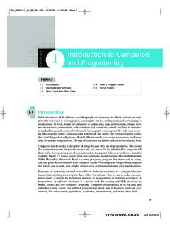
7 The communication can not propa-gate throughout an entire device tree like standard USB additional details see Section , USB Power Delivery MODES (THIRD PARTY PROTOCOLS)The usb type -C cable allows for any third party protocol to be used as long as the cable can support it. Alternate Modes are negotiated and entered on a port-to-port basis using the USB Power Delivery protocol. The following signals may be reassigned when entering an Alternate Mode. TX1+/- RX1+/- TX2+/- RX2+/- SBU1/SBU2 Separate specifications define the rules for each Alternate Mode. Currently, specifications exist for DisplayPort (authored by VESA) and ThunderBolt (authored by Intel). For additional details see Section , Alternate PinsFIGURE 2:GNDSBU2 SBU1CC2 VBUSTX2- TX2+RX2+RX2-VBUSD-D+CC1RX1+GNDRX1-VBUSGN DTX1+ TX1-VBUSD-D+GNDA1 A2 A3 A4 A5 A6 A7 A8 A9 A10 A11 A12B12 B11 B10 B9 B8 B7 B6 B5 B4 B3 B2 B1 usb type -C RECEPTACLEAN1953DS00001953A-page 4 2015 Microchip Technology 3.
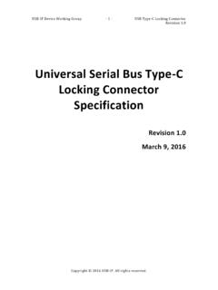
8 GNDVCONNCCSBU2 VBUSRX1- RX1+TX1+TX1-VBUSD+D-SBU1TX2+GNDTX2-VBUSG NDRX2+ RX2-VBUSGNDA12 A11 A10 A9 A8 A7 A6 A5 A4 A3 A2 A1B1 B2 B3 B4 B5 B6 B7 B8 B9 B10 B11 B12 usb type -C PLUGThe usb type -C connector has 24 pins. Because of its reversibility, the pins are arranged in a mirrored configuration. There are a total of 6 differential pairs in a full-featured cable assembly. There are also 4 pins that serve functions new to USB: CC1, CC2, SBU1, DIFFERENTIAL PAIRSThe 2 sets of differential pairs in the connector pinout only connect to a single differential pair in standard or Full Featured usb type -C cables.
9 In a typical design, the D+ and D- pins are simply shorted on the PCB so that a multiplexer or switch is not second set of pins (B6/B7) may only be re-purposed in docking type applications where only 1 orientation is DIFFERENTIAL PAIRSBy default, only one set of TX/RX differential pairs are used for communication, depending on cable insertion orientation. Because of the cable reversibility, the lanes must be rerouted upon orientation connection. A typical application may use a 2:1 multiplexer to achieve Power Delivery protocol and Alternate Modes allow some or all of the TX/RX differential pairs to be PINSThe CC1 and CC2 pins are used to connect to the either the CC or VCONN wire in a usb type -C cable. Both CC1 and CC2 pins must be able to support both CC and VCONN functions.
10 The function is detected upon cable CC wire is used to cable orientation detection, usb type -C current capability advertisement and detection, and BMC communication. See Section , CC Pins for additional VCONN wire is used to power active or electronically marked cables. See Section , VCONN Supply for addi-tional SBU wires are lower speed signal wires that is allocated for Alternate Mode use only. USB Power Delivery is required for Alternate Mode negotiation before these pins may be used for any 1: usb type -C RECEPTACLE PINOUT PinNameFunctionNoteA1 GNDP owerSupport for 60W minimum (combined with all VBUS pins)A2TX1+ or Alternate Mode10Gb/s differential pair with or Alternate Mode10Gb/s differential pair with TX1+A4 VBUSP owerSupport for 60W minimum (combined with all VBUS pins)A5CC1CC or VCONN A6D+ A8 SBU1 Alternate ModeLower speed side band signalA9 VBUSP owerSupport for 60W minimum (combined with all VBUS pins) or Alternate Mode10Gb/s differential pair with RX2+A11RX2+ or Alternate Mode10Gb/s differential pair with RX2-A12 GNDP owerSupport for 60W minimum (combined with all VBUS pins)