Transcription of Using Microcontroller AVR ATmega16 - ijert.org
1 Fault Detection and Protection of single Phase induction motor Using Microcontroller AVR ATmega16 Ms. Thorat Snehal Anuprao Electrical Department JSPM s BSIOTR, Pune, India Assistant Prof. Dusing Priyanka Electrical Department JSPM s BSIOTR, Pune, India Abstract Objective of this paper is to detect faults of single phase IM & control. Due to various reasons single phase induction motor may experience many nascent faults. It's very important to protect motors from such faults. The various faults are over-voltage, under-current, under-voltage, under-current, overload, over-temperature etc. So indentify such faults most important parameters are voltage, current and temperature.
2 Here single phase induction motor is protected Using advanced Microcontroller AVR ATmega16 . For this the variable potentiometer is connected across the circuitry by which we can vary the voltage of the motor . If motor goes beyond certain temperature the motor may be automatically turn off Using temperature sensor LM35. Keywords: Microcontroller AVR ATmega16 , IM ( induction motor ) I. INTRODUCTION Many motors are used in domestic equipments and Industrial machine tools. Electric motors are necessary & indispensable to many industries. These motors perform wide ranging functions as required. induction Motors are used for automation, appliances, induction control; because they are robust, reliable and durable.
3 induction motor runs at estimated speed when power is supplies at recommended specification, but variable speed is required by many applications for their operations. Many types of AC induction motors are available in market. Different applications use different motors as per requirements. An AC induction motors are easier to design than DC motors. induction motors are reliable but they are subjected to undesirable stresses which causes faults resulting in lower efficiency or failures. Incorrect design, short circuits or excessive load leads to these electrically related faults. Due to manmade error or natural occurring events further adds to this.
4 Monitoring of an induction motors is an emerging technology for detection of initial faults and to avoid unexpected failure of an industrial process. However robust, but prone to failure, resulting in downtime which may prove to be very costly [2]. Therefore recently, condition monitoring of electrical machines has received more recognition. Control of parameters like current, voltage, load and temperature is become important for the health of induction motor . Because of faults in such parameters can be damaging to induction motor . Monitoring techniques in IMs uses some combination of mechanical and electrical devices such as current/voltage relays, timers, contactors etc.
5 These basic techniques involve some mechanical dynamic parts of the equipment which can cause problem in course of operation reducing life and efficiency of system. Similarly computer based protection system and PLC based system has been introduced but they also have their limitation like analog to digital conversion module cost etc. Systems based on microprocessor for protection are developed but they lack control action, only display on screen and buzzer is available [1]. II. THE SYSTEM STRUCTURE A. Overall System Architecture Design objectives are faults detection then monitoring and controlling motor .
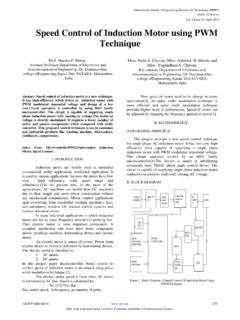
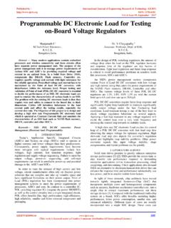
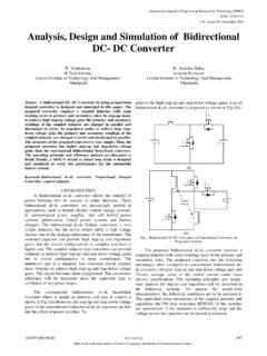
6 Determine the tolerable limit values of voltage, current, speed, temperature. Now obtained tolerable limit value of these parameters are measured and are compared on continuous basis. Transformer is used to step down 230V AC obtained from the supply into 12V AC. The bridge rectifier used to convert 12V AC into DC. Voltage regulator is used to reduce ripples in dc pure DC obtained which is suitable for Microcontroller . Using Microcontroller programming and relay, out of range parameters can be detected, thus we can protect the motor from faults. Here we use current sensor for current measurement.
7 LM35 is used for temperature measurement and potentiometer for voltage measurement [3]. Figure 1. System architecture The whole system can be divided into two parts. First part focuses on rectifier and micro controller. Second part focuses on measurement of motor of parameters like current, voltage and temperature. Heart of system is AVRatMega16. Using Microcontroller , analog parameters are converted into digital. International Journal of Engineering Research & Technology (IJERT)ISSN: 2278-0181 (This work is licensed under a Creative Commons Attribution International License.)Published by 6 Issue 04, April-2017177 III. THE HARDWARE DESIGN A.
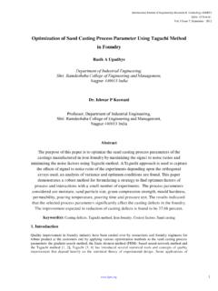
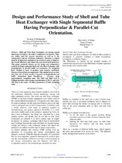
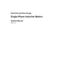
8 single Phase induction motor and Relay Here submersible single phase split phase induction motor of rating 18 watt, which is to be protected. A relay is an electrically operated switch. When current flows through coil of relay, creates a magnetic field which attracts a lever and changes the switch contacts. Relay operating here is SPDT ( single pole double throw), which has 5V DC rating. B. Power supply Power supply circuitry is designed to get the regulated power supply so that the micro controller cannot be damaged. 5V DC is required for suitable operation of the micro controller. A 50Hz, 230V single phase AC power supply is given to a step down transformer to get 12V supply.
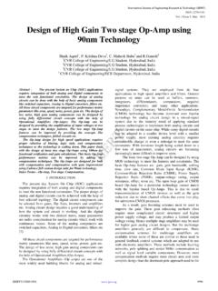
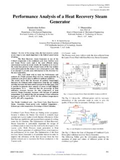
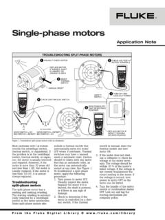
9 Bridge Rectifier is used to convert this voltage to DC voltage. To obtain constant 5v supply, 2200uf capacitor filters the converted pulsating DC voltage and then given to LM7805 voltage regulator. Figure 2. Power supply C. Microcontroller AVR ATmega16 AVR ATmega16 has 1 kb RAM and 16KB Flash RAM which has 4 ports namely PORT A, PORT B, PORT C and PORT D. The micro controller accepts or gives out data Using these ports. It works at 5V, exceeding this voltage at power supply might result in burning of the IC. It is heart of the system; analog signals obtained from different sensors are converted into digital.
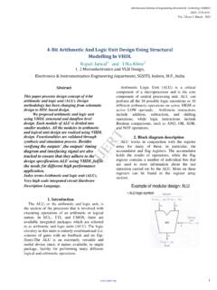
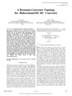
10 Figure 3. Pin Configuration D. Current sensor High current sensitivity of 1 mV/mA with wide operating voltage range 3V ~ 12V, WCS2702 provides precise solution for both DC and AC current sensing in system. It provides analog signal proportional to current, supplied IM which Microcontroller use to determine the status. When applied current flows through this conduction path, it generates a magnetic field and convert into a proportional voltage. Figure 4. Current sensor E. Potentiometer Potentiometer is 1K to 10K rotatory switch potentiometer and can be rotated in clockwise and anticlockwise direction. It uses voltage divider arrangement where rotating switch is called wiper and other terminals called as the ends, used to vary the voltage.