Transcription of VACUUM SYSTEMS - Graham
1 VACUUM SYSTEMS From large to small SYSTEMS , complete packages and hybrid SYSTEMS . Precision made, performance tested and guaranteed. 2 EJECTORS Principles and benefits Ejectors consist of six basic parts: 1. Motive Fluid Chest 2. Converging/Diverging Nozzle 3. Mixing Chamber 4. Converging Inlet Diffuser 5. Diverging Outlet Diffuser 6. Diffuser Throat The operating principle of the ejector is that the pressure energy in the motive fluid (1) is converted to velocity energy by an adiabatic expansion in the Converging/Diverging Nozzle (2).
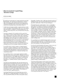
2 The Nozzle exit velocity is normally in the supersonic range of 3000 to 4000 feet/second when using steam as the motive fluid. (Velocities may vary depending on molecular weight, temperature, and pressure of the motive fluid.) This high-velocity (cone shaped) jet enters the Mixing Chamber (3) and entrains the suction fluid being pumped. The mixture attains a velocity of approximately 2000 to 3000 feet per second. The mixed motive fluid and suction fluid then enter the Converging Inlet Diffuser (4) where a portion of the velocity energy is converted to pressure energy.
3 The mixture is then compressed in the Diverging Outlet (5) s ection of the Diffus er to attain the final discharge pressure, normally 5 to 15 times the suction pressure. There is a corresponding rise in mixture temperature as this com pression occurs. EJECTOR BENEFITS Ejectors can be operated with many different motive fluids: steam, air, organic vapor and other gases. Can handle corrosive and slugging liquids, solid and abrasive suction fluids without damage. Simple, rugged, reliable and trouble-free. No moving parts, no lubrication, no vibration, no bearing or seal problems.
4 (Available with flanged or weld end connections.) Explosion-proof construction. Ejectors can be installed indoors or outdoors with versatile mounting design. Low initial cost, low maintenance cost, long life. Can handle high volumes of suction fluid at low absolute pressures. Graham has built single-stage ejectors to handle 575,000 CFM at 100 TORR, and six-stage ejectors to handle 130,000 CFM at TORR (10 microns ABS). Graham ejectors are precision-machined and performance-tested. 6. Diffuser Thr oat 5. D i ver gi ng Outl et Diffuser 4.
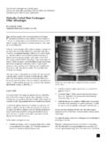
5 C onver gi ng Inlet Diffuser 3. M i xi ng C hamber 2. C onver gi ng/D i ver gi ng Nozzle 1. Motive Fl ui d C hest 3 LIQUID RING VACUUM PUMP Principles and benefits Next to ejectors, Liquid Ring VACUUM Pumps are the most used VACUUM -producing devices in industry. Graham manufactures a complete line of these pumps in our own factory. The operating principle of the liquid ring VACUUM pump is that the only moving part is an eccentrically mounted impeller within a ring of liquid. Pump action is created by increasing and decreasing spaces between the impeller blades and liquid ring.
6 Process gases enter and leave these spaces (impeller buckets) through adjacent ports in sideplates next to the impeller. These single- or two-stage pumps can achieve pressure ranges from atmospheric to 25 TORR. Graham units offer design simplicity, high efficiency, low maintenance, and the capability to handle wet corrosive process streams. A complete line of spare parts is always available at our Batavia, NY plant. Applications: Liquid ring VACUUM pumps are used in the Refining Industry-for crude oil VACUUM distillation, lube oil dryers, and for asphalt production; and in the Power Industry to evacuate steam surface condensers.
7 Other industries (food, chemicals, pharmaceuticals, hospitals, pulp & paper, etc.) use liquid ring VACUUM pumps extensively. LIQUID RING VACUUM PUMP BENEFITS Reliable, simple design involves only one rotating part, which is not subject to wear. Can handle condensible vapors or even slugs of liquid entrained in the gas stream without damage to the pump or affecting performance. Produces a steady non-pulsating gas flow when it is used as either a VACUUM pump or compressor. Resistant to contaminants entering with the gas stream; these will be diluted and washed through the pump by the seal liquid.
8 Wide choice of materials are readily available for handling most gases and seal liquids. Can handle volumes from 3 to 4000 ACFM over a VACUUM range from atmospheric to 25 TORR. Also totally compatible with steam ejectors for higher vacuums and flow rates. Graham pumps are precision made and performance guaranteed. Outlet port Inle t port Impeller Interstage Crossover Manifold Shaft Extension Bearing/Mechanical Seal Housing Impeller casing 1st Stage Impeller Side plates End casing 2nd Stage Impeller 4 VACUUM SYSTEMS Types and pressure ranges Ejector SYSTEMS : Ejector SYSTEMS are made up of a number of ejector stages in series with condensers (direct contact or surface type) between stages to condense the load and motive fluids where temperature and pressure permit.
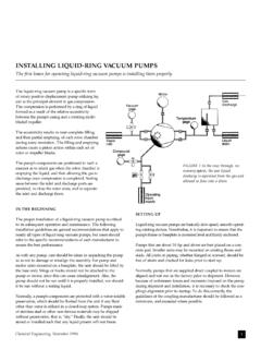
9 Since Ejectors are a fixed-capacity device, various parallel-series arrangements are used to accomplish process load control and pressure control. Fig. 1 shows a schematic arrangement for a six-stage ejector system compressing non-condensibles to a positive pressure. It also indicates a Graham Liquid Ring VACUUM Pump that can be used to replace the final two Ejector stages. Choice of equipment is generally determined by cost factors. Approximate pressures at the suction and discharge of each stage are shown on the Figure 2 schematic.
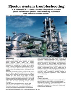
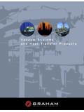
10 Fig. 2 can be used to estimate the number of stages required for a given application. For example, if the desired pressure is 1 TORR, the chart shows this in the middle of the four-stage range. At TORR, a four- or five-stage unit is indicated. Selection is usually determined by comparing initial costs and utilities cost. Fig. 3 shows the approximate steam consumption per pound of air load for various SYSTEMS as a function of dry air handling capacity. Fig. 3 ALTERNATE CONDENSING STAGES NONCONDENSING STAGES LRVP INTERCONDENSERINTERCONDENSERINTERCONDENS ER10006 STAGE 5 STAGE 4 STAGE 3 STAGE 2 STAGE 1 STAGE RATIO (PPH MOTIVE STEAM PER PPH AIR LOAD) 10010011110.