Transcription of Valtek Beta Positioners for Control Valves
1 24-1 Flowserve Corporation, Valtek Control Products, Tel. USA 801 489 8611 Valtek No. 49035 Valtek Beta PositionersGeneral InformationThis bulletin contains instructions for installing, cali-brating, troubleshooting, and performing maintenanceas required for the Valtek Beta positioner mounted oncontrol for maintaining and calibrating the NT 3000I/P module are contained in Installation, Operation,Maintenance Instructions 47, NT 3000 Series electro - pneumatic transducer Module. For calibration andmaintaining the remote I/P see Installation, Operation,and Maintenance Instructions 30, users and maintenance personnel should readthoroughly and follow exactly the instructions containedin this bulletin prior to operation of the positioner . If thereis any question concerning this bulletin, call your avoid possible injury to personnel or dam-age to equipment, WARNING and CAUTION notes must be strictly adhered to.
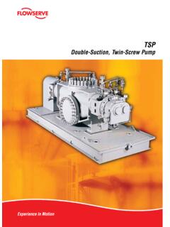
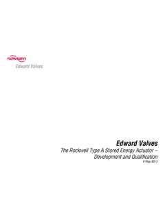
2 Modifyingthis product, substituting non-factory or infe-rior parts, or using maintenance proceduresother than outlined could drastically affect per-formance, be hazardous to personnel andequipment, and may void existing : Numbers in parenthesis correspond to the partitem numbers in Figure positioner OverviewThe Valtek Beta positioner is available with either a pneumatic (P/P) module for air Control signals or an electro - pneumatic (I/P) module for milliampere electri-cal Control signals. It is double-acting, capable of sup-plying air to either side of the actuator piston while exhausting the other side to the atmosphere. The Valtek Beta positioner can be interchanged with the 80R and XL Positioners without changing the brackets or takeoff Beta positioner with I/P module is intrinsically safefor FM/CSA class 1, division I, groups A, B, C, and D;class II, groups E, F, and G, and CENELEC EEx ia IIc,when installed with the appropriate energy limitingsafety barriers (See Figure 1).
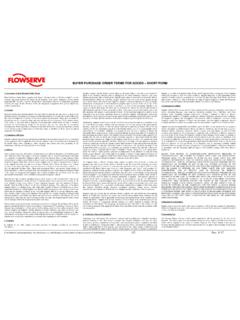
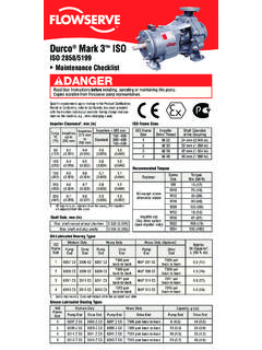
3 It is also explosion prooffor FM/CSA class II, groups E, F, and G, and CENELECEEX d IIb + H2. Since the positioner is insensitive tosupply pressure changes and can handle supply pres-sures from 30 to 150 psi a supply regulator is usually notrequired; however, an air filter is highly : The air supply should conform to ISA (a dew point at least 18 F below ambient tempera-ture, particle size below 5 microns, oil content not toexceed 1 part per million). positioner OperationThe Beta positioner is a force-balanced 2 shows a Beta positioner , with either a pneu-matic or electro - pneumatic (I/P) module, installed on adouble-acting actuator for air-to-open action. Position-ing is based on a balance of two forces; one proportionalto the instrument signal and the other proportional to thestem the I/P model, the current signal is first convertedto a 3-15 psi air signal. For the pneumatic model, the3-15 psi signal is passed directly into the positioner .
4 Thepressure signal acts upon the diaphragms in the instru-ment signal capsule creating a downward force. Themotion of the actuator stem is transmitted to the top endof the feedback spring through the follower arm andcams. As a result, tension in the feedback spring willvary as the stem position Control Valves24-2 Flowserve Corporation, Valtek Control Products, Tel. USA 801 489 8611 Figure 1: Intrinsically Safe Installation SchematicFigure 2: positioner Schematic for Air-to-Open (Retract)24-3 Flowserve Corporation, Valtek Control Products, Tel. USA 801 489 8611A decrease in the instrument signal reverses the de-scribed actions causing a proportional downward move-ment of the actuator piston and spool has a close tolerance to the block and a smallamount of air, SCFM, will exhaust at the null, orequilibrium, position. This air consumption is Module OperationThe I/P module receives a 30-150 psi air supply pres-sure from the Beta positioner and converts it to a 3-15 psioutput signal.
5 This signal is proportional to a 4-20 mAinput signal or a 10-50 mA input signal depending on themodel supply pressure from the Beta positioner is filteredas it passes through a field-replaceable, coalescing filterelement in the module. Next it passes through aninternal pressure regulator that regulates it to approxi-mately 22 psi. The air then goes through an orifice thatrestricts the flow and air air is further controlled to 3-15 psi using a spring-diaphragm flapper that is attracted by an electromagnetto a nozzle. A temperature compensated piezoresistivepressure sensor mounted on a circuit board senses theI/P output pressure. The pressure sensor and circuitrycreate a feedback loop, which determines how muchcurrent to send to the electromagnet for a desiredpressure output. The electromagnet in the feedbackloop varies the nozzle-flapper spacing, which regulatesthe I/P output pressure to 3-15 psi proportional to the4-20 (or 10-50 mA) input these opposing forces balance exactly, the sys-tem will be in equilibrium and the stem will be in theposition called for by the instrument signal.
6 If theseopposing forces are not in balance, the summing beamwill move up (or down) and, by means of the spool valve,will change the output pressures and flow rate. This willcause the piston to move until tension on the feedbackspring equalizes with the instrument signal detailed sequence of positioner operations are asfollows: An increase in the instrument signal forces theinstrument signal capsule and summing beam down-ward. This motion of the summing beam also pulls thepilot valve spool downward from its equilibrium opens the pilot valve ports, supplying air to port 1and exhausting air from port 2. This causes the actuatorpiston to move upward motion of the piston is transmitted back tothe positioner through the feedback linkage and camresulting in the spring being stretched proportionally tothe valve position. The piston continues to stroke up-ward until the force in the feedback spring increasessufficiently to counter the force generated by the instru-ment signal capsule.
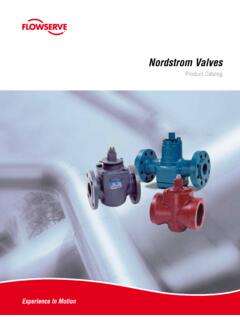
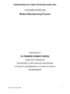
7 At this point, the summing beamand spool begin to return to their equilibrium the valve spool ports start to close, the air flow rateto the actuator is the piston has reached the required position, thefeedback spring tension force will equal the force gen-erated in the instrument signal capsule. The summingbeam and instrument signal capsule will remain in theirequilibrium positions with no air flowing to the actuatoruntil a change in the instrument signal is 3: positioner Mounted on Mark One with Linear ActuatorFollower ArmStem ClampTake-off Arm24-4 Flowserve Corporation, Valtek Control Products, Tel. USA 801 489 8611 Hole AL-RL-D Air-to-OpenAir-to-Close (Air-to-Retract)(Air-to-Extend)Figure 6: Return Spring / Cam Mounting(viewed from positioner s right side)PositionerBaseReturn SpringHole BCamInstallationThe installation section of this bulletin details how toinstall the positioner on linear and rotary the air action on linear and rotary actuators isalso covered along with an explanation of how to con-vert the positioner from an I/P to pneumatic or pneu-matic to I/P Control positioner on Linear ActuatorsInformation for installing or retrofitting the Beta Posi-tioner on all sizes of linear actuators follows:Figure 4: Beta positioner with pneumatic ModuleZero AdjustmentKnobZero AdjustmentLocking KnobRange AdjustmentLocking ScrewFeedback SpringPneumaticModuleRange AdjustmentGearRange ArmCamSpool ValveInstrument SignalCapsuleNOTE.
8 When retrofitting the Beta positioner to anactuator equipped with a Moore or comparable posi-tioner, remove the existing positioner , bracket, stemclamp, and associated bolting. If retrofitting to an actua-tor equipped with a Valtek Beta pneumatic , system 80,or XL positioner , the same bracket, stem clamp, andbolting can be Place the new stem clamp (if applicable) onto theactuator stem with the boss on the right side asillustrated in Figure Mount the positioner bracket to the yoke leg whichhas the stroke indicator plate attached to it and inthe correct position as shown in Figure 25, 100, 200 Size 50 Figure 5: Mounting Bracket24-5 Flowserve Corporation, Valtek Control Products, Tel. USA 801 489 8611 Figure 7: Beta positioner with NT 3000 Transducer3. If not welded to the stem clamp, bolt the take-off armto the stem clamp so that the arm curves upward(toward the cylinder).
9 The holes in the follower arm(31) should line up with the slots in the take-off arm(again refer to Figure 3).4. Referring to Figure 6, install the cam (27), cam shaft(29) and follower arm (31) for the proper air air-to-open action, the cam should be installedwith the letters L-R facing toward the cam shaft andthe return spring should be fed into hole A. For air-to-close action, the L-D side of the cam should facetoward the cam shaft and the return spring shouldbe fed into hole B. 5. Feed the appropriate stroke follower arm (31) ontothe cam shaft boss (29) with the hole markingsfacing outward. Fasten securely with the lockwasher (32) and nut (33).6. Mount positioner on the bracket. Connect thefollower arm (31) and take-off arm together withfollower pin (62). Connection must allow freemovement of follower : Be certain to lubricate the followerpin and take-off arm where contact is made toprevent premature wear.
10 A light industrialgrease is recommended. Failure to do so cancause premature wear, resulting in equipmentfailure and possible personal For air-to-open (air-to-retract) air action, tube out-put 1 to the bottom and output 2 to the top of thecylinder. For air-to-close (air-to-extend) action, tube output 2 to the bottom and output 1 to the top ofthe Attach air supply and instrument tubing, using 1/4-inch NPT tubing : A 3-15 psi instrument signal is rec-ommended on the pneumatic module. High airpressure may damage the module; the moduleis limited to 30 Air Action on Linear ActuatorsReversing the air-action of the positioner is simple. Noadditional parts are required, although the tubing willneed to be rerouted on the linear reverse the air-action on all sizes of Valtek linearactuators:1. Using Installation, Operation, Maintenance Instruc-tions 2, reverse the air-action of the Disengage the return spring from the cam andremove the cam from the cam Reverse the cam, return spring, and tubing for thedesired air-action by referring to steps 4-8 in the Installing positioner on Linear Actuators section ofthis AdjustmentSpan AdjustmentMinimum PressureCutoff AdjustmentCurrent LoopTermination (+)Current LoopTermination (-)Terminal BlockRangeAdjustmentGearVent ScreenSpool ValveGrounding ScrewZero Adjustment KnobRange ArmCamZero Adjustment LockingZero ArmRange AdjustmentLocking ScrewFeedback SpringInstrument SignalCapsuleMounting Screws24-6 Flowserve Corporation, Valtek Control Products, Tel.