Transcription of Variable Volume and Temperature - …
1 VariableVolumeandTemperatureCOMMERCIAL HVACSYSTEMS Technical Development Program Technical Development Programs (TDP) are modules of technical training on HVAC theory, system design, equipment selection and application topics. They are targeted at engineers and designers who wish to develop their knowledge in this field to effectively design, specify, sell or apply HVAC equipment in commercial applications. Although TDP topics have been developed as stand-alone modules, there are logical group-ings of topics. The modules within each group begin at an introductory level and progress to ad-vanced levels.
2 The breadth of this offering allows for customization into a complete HVAC cur-riculum from a complete HVAC design course at an introductory-level or to an advanced-level design course. Advanced-level modules assume prerequisite knowledge and do not review basic concepts. VVT is an economical, all-air zoned system that is ideal for many commercial jobs, espe-cially at a time when there is so much design emphasis being placed on high-quality air treatment, outdoor air ventilation, and room air circulation. VVT systems are a popular solution for heating and cooling multiple zone applications in small to medium size buildings. VVT controls typically are supplied pre-packaged from the HVAC equipment supplier and are ready to install by the me-chanical contractor.
3 Many manufacturers offer VVT-type systems. These systems are highly de-pendent on the control hardware and software used. This TDP uses the Carrier VVT system for all examples. The objective of this module is to define VVT, identify applications, compare it to alternative systems, and describe how it achieves zone Temperature control. 2004 Carrier Corporation. All rights reserved. The information in this manual is offered as a general guide for the use of industry and consulting engineers in designing sys-tems. Judgment is required for application of this information to specific installations and design applications. Carrier is not re-sponsible for any uses made of this information and assumes no responsibility for the performance or desirability of any resulting system design.
4 The information in this publication is subject to change without notice. No part of this publication may be reproduced or transmit-ted in any form or by any means, electronic or mechanical, for any purpose, without the express written permission of Carrier Corporation. Printed in Syracuse, NY CARRIER CORPORATION Carrier Parkway Syracuse, NY 13221, Table of Contents 1 The VVT System .. 4 VVT is Variable Volume .. 6 VVT is Variable Temperature ..6 What is Zoning?.. 7 Types of VVT Jobs .. 8 Jobs at 25 Tons or Less .. 8 Jobs Larger than 25 Tons .. 9 Retrofitting Existing Systems with VVT .. 10 VVT versus Other 13 VVT Advantages .. 14 VAV System Comparisons.
5 16 VVT versus Multiple 18 Zoning the Building for VVT .. 19 Basic Sequence of Operation .. 22 Linkage .. 23 Pressure Dependent (PD) versus Pressure Independent (PI) .. 23 Call for Heat/Cool and Equipment Mode .. 24 System Changeover .. 25 Selecting Zone Priority - Reference 26 Fan Sequence of Operation .. 26 VVT Air Distribution System 27 Sealing VVT Ducts .. 30 Dampers .. 31 Round Dampers .. 32 Rectangular Bypass System 32 Bypass Functionality .. 33 Layout .. 34 Damper Sizing .. 36 Diffuser 37 Control System Details .. 40 Linkage Coordinator versus Standard Zone 40 Bypass Controller .. 41 The System Pilot .. 41 Space Sensor Locations and Options.
6 42 Combined Space Temperature and CO2 43 Humidity Sensor .. 43 Zone Sensor 43 Outside Air Temperature Sensor .. 43 Zone Level Demand Controlled Ventilation (DCV).. 44 Zoning Systems with DCV .. 44 Wiring and Power Requirements .. 45 System Options .. 45 Supplemental and Perimeter 46 Summary .. 49 Work Session .. 50 Designer Checklist .. 52 Engineering Design Steps .. 52 Installation Notes for Contractors ..54 VVT Installation Start-up Request 56 Work Session Answers .. 58 Variable Volume AND Temperature Commercial HVAC Systems 1 Introduction VVT ( Variable Volume and Temperature ) is an economical, all-air zoned system that is ideal for many commercial jobs, especially at a time when there is so much design emphasis being placed on high quality air treatment, outdoor air ventilation, and room air circulation.
7 When a single heating/cooling unit is used, VVT works well for systems up to about 25 tons of total cool-ing capacity. Multiple systems make its application practical for much larger jobs. This module defines VVT and describes how it achieves zone Temperature control. Applica-tions for the system will be identified and VVT will be compared with alternative systems. Since the operation of the VVT system is under the direction of a complete, factory-packaged DDC (direct digital control) control system, various pre-programmed, operational sequences will be described so that the way it works will be clear. Guidelines for VVT system design are given so that the designer may focus on some of the unique aspects of the system.
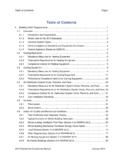
8 Air conditioning design is all about solving building comfort needs to satisfy the occupants of that building. One of the buildings we will use to illustrate zoning and the use of VVT is this manufacturing office, which is a 60 x 100 single-story commercial construction attached to a small, air-conditioned elec-tronics manufacturing and assembly factory. This is an owner-occupied office with relatively permanent partition arrangement and an expectation for a rea-sonably good level of com-fort. Occupants will be ex-posed to the indoor envi-ronment for long periods of time, so their comfort ex-pectation will tend to be high.
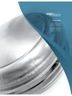
9 In addition, they are sedentary, for the most part, which increases their sensitivity to variations in Temperature , air distribu-tion and air stratification. Figure 1 Manufacturing Office Example Building Variable Volume AND Temperature Commercial HVAC Systems 2 Figure 2 60 x 100 Manufacturing Office VVT System Layout Variable Volume AND Temperature Commercial HVAC Systems 3 The task of the air- conditioning system is to maintain comfort in the building by simultane-ously controlling space Temperature , humidity, air motion, air purity, air quality, and mean radiant Temperature .
10 In our case, the system will be a VVT system. The layout shown in Figure 2 in-cludes many details for a real design. In a sense, this is your map for the information that is coming. It will help you to focus on the area of the system being addressed in virtually every por-tion of this module. Take a few minutes to look the layout over, reading the designer s system comments, which describe the VVT system designed for this job. For this VVT system, a single heating/cooling, constant Volume packaged rooftop unit pro-vides central heating or cooling capacity to the VVT boxes. Each box modulates its Volume con-trol damper in response to the zone thermostat or sensor.