Transcription of Verilog 1 - Fundamentals
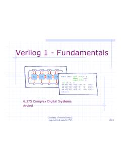
1 Verilog 1 - Fundamentals FA FA FA FA module adder( input [3:0] A, B, output cout, output [3:0] S );. wire c0, c1, c2;. FA fa0( A[0], B[0], 1'b0, c0, S[0] );. FA fa1( A[1], B[1], c0, c1, S[1] );. FA fa2( A[2], B[2], c1, c2, S[2] );. FA fa3( A[3], B[3], c2, cout, S[3] );. endmodule UCSD CSE 141L Taylor Heavily modified; descended from MIT's What is Verilog ? ! In this class and in the real world, Verilog is a specification language, not a programming language. Draw your schematic and state machines and then transcribe it into Verilog . When you sit down to write Verilog you should know exactly what you are implementing. ! We are constraining you to a subset of the language for two reasons These are the parts that people use to design real processors Steer you clear of problematic constructs that lead to bad design.
2 Verilog Fundamentals ! What is Verilog ? ! Data types ! Structural Verilog ! RTL Verilog Combinational Logic FA FA FA FA. Sequential Logic module adder( input [3:0] A, B, output cout, output [3:0] S );. wire c0, c1, c2;. FA fa0( A[0], B[0], 1'b0, c0, S[0] );. FA fa1( A[1], B[1], c0, c1, S[1] );. FA fa2( A[2], B[2], c1, c2, S[2] );. FA fa3( A[3], B[3], c2, cout, S[3] );. endmodule Bit-vector is the only data type in Verilog A bit can take on one of four values Value Meaning 0 Logic zero In the simulation waveform viewer, 1 Logic one Unknown signals X Unknown logic value are RED. There should be no red Z High impedance, floating after reset. An X bit might be a 0, 1, Z, or in transition. We can set bits to be X in situations where we don't care what the value is.
3 This can help catch bugs and improve synthesis quality. wire is used to denote a hardware net wire [15:0] instruction; Absolutely no type wire [15:0] memory_req; safety when wire [ 7:0] small_net; connecting nets! ? memory_req instruction instruction small_net Bit literals ! Binary literals 4'b10_11 8'b0000_0000. 8'b0xx0_1xx1. Underscores ! Hexadecimal literals are ignored 32'h0a34_def1. Base format 16'haxxx (d,b,o,h) . ! Decimal literals Decimal number 32'd42. representing size in bits We'll learn how to actually assign literals to nets a little later Verilog Fundamentals ! History of hardware design languages ! Data types ! Structural Verilog ! RTL Verilog FA FA FA FA. module adder( input [3:0] A, B, output cout, output [3:0] S ).
4 Wire c0, c1, c2;. FA fa0( A[0], B[0], 1'b0, c0, S[0] );. FA fa1( A[1], B[1], c0, c1, S[1] );. FA fa2( A[2], B[2], c1, c2, S[2] );. FA fa3( A[3], B[3], c2, cout, S[3] );. endmodule Note: Our Verilog Subset ! Verilog is a big language with many features not concerned with synthesizing hardware. ! The code you write for your processor should only contain the languages structures discussed in these slides. ! Anything else is not synthesizable, although it will simulate fine. ! You MUST follow the course coding standard;. a document will be released soon. ! We will be mixing in some synthesizable SystemVerilog later in the course to improve maintainability of your code. A Verilog module has a name and a port list a_i b_i module adder( input [3:0] a_i, 4 4 input [3:0] b_i, output cy_o, output [3:0] sum_o ).
5 Adder // HDL modeling of // adder functionality 4. endmodule cy_o sum_o Ports must have a direction Note the semicolon and a bitwidth. In this at the end of the port class we use _i to denote in list! port variables and _o to denote out port variables. A module can instantiate other modules a_i b_i adder FA FA FA FA. cy_i sum_o a_i b_i module adder( input [3:0] a_i, b_i, cy_o FA cy_i output cy_o, output [3:0] sum_o ); sum_o wire c0, c1, c2;. FA fa0( .. ); module FA( input a_i, b_i, cy_i FA fa1( .. ); output cy_o, sum_o);. FA fa2( .. ); // HDL modeling of 1 bit FA fa3( .. ); // full adder functionality endmodule endmodule Connecting modules A B. adder FA FA FA FA. cout S. module adder( input [3:0] a_i, b_i, output cy_o, output [3:0] sum_o ).
6 Wire c0, c1, c2;. FA fa0( a_i[0], b_i[0], 1'b0, c0, sum_o[0] );. FA fa1( a_i[1], b_i[1], c0, c1, sum_o[1] );. FA fa2( a_i[2], b_i[2], c1, c2, sum_o[2] );. FA fa3( a_i[3], b_i[3], c2, cy_o, sum_o[3] );. Carry Chain endmodule This class's style standard: Connect ports by name and not by position. Connecting ports by ordered list is compact but bug prone: FA fa0( a_i[0], b_i[0], 1'b0, c0, sum_o[0] );. Connecting by name is less compact but leads to fewer bugs. This is how you should do it in this class. You should also line up like parameters so it is easy to check correctness. FA fa0( .a_i(a_i[0]). Connecting ports by name ,.b_i(b_i[0]). yields clearer and less buggy ,.cy_i(1'b0) code. In the slides, we may ,.cy_o(c0) do it by position for space.)
7 ,.sum_o(sum_o[0]) But you should do it by name ); and not position. Verilog Fundamentals ! History of hardware design languages ! Data types ! Structural Verilog ! RTL. Combinational FA FA FA FA. Sequential module adder( input [3:0] A, B, output cout, output [3:0] S );. wire c0, c1, c2;. FA fa0( A[0], B[0], 1'b0, c0, S[0] );. FA fa1( A[1], B[1], c0, c1, S[1] );. FA fa2( A[2], B[2], c1, c2, S[2] );. FA fa3( A[3], B[3], c2, cout, S[3] );. endmodule A module 's behavior can be described in many different ways but it should not matter from outside Example: mux4. mux4: Using continuous assignments to generate combinational logic module mux4( input a_i, b_i, c_i, d_i, Language defined input [1:0] sel_i, operators output z_o ).
8 Wire t0, t1;. assign z_o = ~((t0 | sel_i[0]) & (t1 | ~sel_i[0]));. assign t1 = ~((sel_i[1] & d_i) | (~sel_i[1] . assign t0 = ~((sel_i[1] & c_i) | (~sel_i[1] . endmodule The order of these continuous assignment statements in the source code does not matter. But it does affect readability! They essentially happen in parallel; also, any time an input is changed, each line is automatically re- evaluated. (Be careful not to create cycles!). mux4: Using ? : // Four input multiplexer module mux4( input a_i, b_i, c_i, d_i, input [1:0] sel_i, output z_o);. assign z_o = ( sel_i == 0 ) ? a_i : ( sel_i == 1 ) ? b_i : ( sel_i == 2 ) ? c_i : ( sel_i == 3 ) ? d_i : 1'bx;. endmodule Not required for synthesis, but helps in simulation: If sel_i is undefined we want to propagate that information in waveform viewer.))))
9 Mux4: Using combinational always_comb or always @(*) block module mux4( input a_i, b_i, c_i, d_i, input [1:0] sel_i, output reg z_o );. reg t0, t1;. always_comb // system Verilog ; equiv. to always begin t0 = (sel_i[1] & c_i) | (~sel_i[1] . t1 = ~((sel_i[1] & d_i) | (~sel_i[1] . t0 = ~t0;. z_o = ~( (t0 | sel_i[0]) & (t1 | ~sel_i[0]) );. end Within the always @(*) begin/end block, effects endmodule of statements appear to execute sequentially; Outside of block, only the last assignment to each variable is visible, and it appears a short time after any input is changed. For instance, the second t0 line uses t0 from the first. Always @(*) permit more advanced combinational idioms module mux4( input a_i,b_i,c_i,d_i input [1:0] sel_i, output reg z_o).)))
10 Always_comb begin if (sel_i == 2'd0 ). z_o = a_i; always_comb else if (sel_i == 2'd1) begin z_o = b_i; case ( sel_i ). else if (sel_i == 2'd2) 2'd0 : z_o = a_i;. z_o = c_i; 2'd1 : z_o = b_i;. else if (sel_i == 2'd3) 2'd2 : z_o = c_i;. z_o = d_i; 2'd3 : z_o = d_i;. else default : z_o = 1'bx;. z_o = 1'bx; endcase end end endmodule endmodule What happens if the case statement is not complete? module mux3( input a_i, b_i, c_i, input [1:0] sel_i, output reg z_o );. always @( * ). begin case ( sel_i ) If sel = 3, mux will output 2'd0 : z_o = a_i;. 2'd1 : z_o = b_i;. the previous value! 2'd2 : z_o = c_i;. endcase What have we created? end endmodule What happens if the case statement is not complete? module mux3( input a_i, b_i, c_i input [1:0] sel_i, output reg z_o ).