Transcription of VFCP Series (Z-Foil) - Datasheet - vishaypg.com
1 Series (Z- foil ) (0805, 1206, 1506, 2010, 2512)For any questions, contact No.: 63106 Revision: 19-Oct-2015 Ultra High-Precision Z- foil Flip Chip ResistorVFCP Series (Z- foil ) (0805, 1206, 1506, 2010, 2512)Ultra High-Precision Z- foil Flip Chip Resistorwith TCR of ppm/ C, 35% Space Saving vs. Wraparound Designand PCR of 5 ppm at Rated PowerDocument No.: 63106 Revision: 19-Oct-2015 FEATURES Temperature coefficient of resistance (TCR): ppm/ C typical ( 55 C to +125 C, +25 C ref.) Tolerance: to (100 ppm) Power coefficient R due to self heating 5 ppm at rated power Load-life stability (70 C for 2000 h): (50 ppm) Power rating to: 600 mW at +70 C Electrostatic discharge (ESD): at least to 25 kV Resistance range: 5 to 125 k (for lower and higher values, please contact us) Bulk Metal foil resistors are not restricted to standard values; specific as required values can be supplied at no extra cost or delivery ( , 1K2345 vs.)
2 1K) Non-inductive, non-capacitive design Thermal stabilization time: <1 s (within 10 ppm of steady state value) Short time overload: (50 ppm) Non hot spot design Rise time: 1 ns effectively no ringing Current noise: < Vrms / V of applied voltage (< 40 dB) Voltage coefficient: < ppm/V Non-inductive: < H Terminal finishes available: lead (Pb)-free, tin/lead alloy Compliant to RoHS directive 2002/95/EC* Matched sets are available per request Rapid prototype sample quantities are available. For more information, please contact us at on VFR s Bulk Metal Z- foil technology, the vfcp Series ( foil resistor flip-chip) excels over all previous stability standards for precision resistors with an order of magnitude improvement in high-temperature stability, load-life stability, and moisture resistance. These new benchmark levels of performance provide design engineers with the tools to build circuits not previously achievable while reducing costs and space in the most critical applications by eliminating the need for corrective circuitry and reducing the large land patterns needed for a wrap-around configuration.
3 The device s flip-chip configuration saves up to 35% PCB space compared with a surface-mount chip with wraparound terminations while also providing better strain relief to eliminate cracked substrates and board addition to its remarkably improved load-life stability, the vfcp Series is noise-free and provides ESD protection of 25 kV or more for increased reliability. The device s solid element alloy is matched to the substrate, forming a single entity with balanced resistance versus temperature characteristics for an unusually low and predictable TCR over a wide temperature range from 55 C to more than +125 C. The adhesive that holds the foil to the flat substrate withstands high temperatures, pulsing power, moisture incursions, shock and vibration, and low-temperature exposure while still holding securely to the foil element. Resistance patterns are photo-etched into the element to permit the trimming of resistance values to very tight tolerances as low as Flip Chips devices are qualified as anti-sulfurated resistors for use in environments with high levels of contamination.
4 Such environments include alternative energy applications, industrial control systems, sensors, RTDs, electric instrumentation, weather and communication base stations, and any electronic appliance used in high concentrations of sulfur. The combination of flip-chip terminations and Z- foil construction and materials results in the most stable resistors available, requiring the lowest error allowance. This means that more error allowance can be transferred to active devices resulting in lower costs or applied to the foil resistors themselves, allowing for looser initial tolerances than would be required for other resistor technologies. RELATED VIDEOR efer to Bulk Metal foil Resistor TCR Performance (Product Demo).* This Datasheet provides information about parts that are RoHS-compliant and/or parts that are non-RoHS-compliant. For example, parts with lead (Pb) terminations are not RoHS compliant.
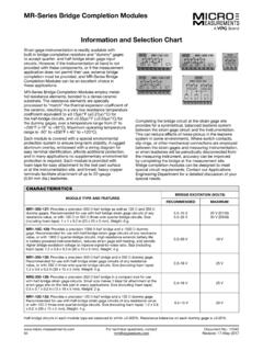
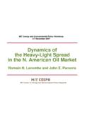
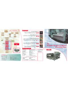
5 Please see the information/tables in this Datasheet for details. Series (Z- foil ) (0805, 1206, 1506, 2010, 2512)For any questions, contact No.: 63106 Revision: 19-Oct-2015 TABLE 1 TOLERANCE AND TCR VALUER esistance Value( )Tolerance (%)Typical TCR and Max. Spread ( 55 C to +125 C, +25 C Ref.)(ppm/ C)250 to 125k to <250 to <100 to <50 to <25 to <10 1 POWER DERATING CURVE1007550250 75 50 250+25+50+75+100+125+150+175 Ambient Temperature ( C) Percent of Rated Power+70 C 55 CFIGURE 2 NOMINAL RESISTANCE/TEMPERATURE CURVE+500+200+1000 100 200 300 500 Ambient Temperature ( C) and TCR Chord Slopes for Different Temperature Ranges RR(ppm) ppm/ C- ppm/ ppm/ ppm/ ppm/ C- ppm/ C 400+300+400 55 25 0 +25 +60 +75 +100 +125 Note The TCR values for <100 are influenced by the termination composition and result in deviation from this 3 TRIMMING TO VALUES (conceptual illustration)
6 Mutual inductancereduction due to change in current directionCurrent pathbefore trimmingFoil shown in black, etched spaces in whiteInterloop capacitancereduction in seriesTrimming processremoves this materialfrom shorting strip areachanging current pathand increasingresistanceCurrent path after trimmingNoteTo acquire a precision resistance value, the Bulk Metal foil chip is trimmed by selectively removing built-in shorting bars. To increase the resistance in known increments, marked areas are cut, producing progressively smaller increases in resistance. This method reduces the effect of hot spots and improves the long-term stability of VFR 2 MODEL SELECTIONChip SizeRated Powerat +70 C (mW)Maximum Voltage Rating( P R)ResistanceRange ( ) (mg)0805100 mW28 V5 to mW79 V5 to mW95 V5 to 30k122010400 mW167 V5 to 70k252512600 mW220 V5 to 125k35 TABLE 3 LOAD-LIFE STABILITY(+70 C for 2000 h)Chip SizeMAXIMUM R LIMITS0805 at 50 mW at 100 mW1206 at 150 mW at 250 mW1506 at 150 mW at 300 mW2010 at 200 mW at 400 mW2512 at 500 mW at 600 mWVFCP Series (Z- foil ) (0805, 1206, 1506, 2010, 2512) Series (Z- foil ) (0805, 1206, 1506, 2010, 2512)For any questions, contact No.
7 : 63106 Revision: 19-Oct-2015 TABLE 4 PERFORMANCE SPECIFICATIONSTest or ConditionMIL-PRF-55342 Characteristic E R LimitsTypical R LimitsMaximum R Limits(1)Thermal Shock (50 ppm) (100 ppm)Low Temperature Operation (50 ppm) (100 ppm)Short Time Overload (50 ppm) (100 ppm)High Temperature Exposure (100 ppm) (200 ppm)Resistance to Soldering Heat (50 ppm) (150 ppm)Moisture Resistance (50 ppm) (300 ppm)Load Life Stability +70 C for 2000 hours at Rated Power (50 ppm) (100 ppm)Note (1) As shown + ohms ( ) to allow for measurement errors at low values. TABLE 5 DIMENSIONS AND LAND PATTERN in inches (millimeters)DWLL1 (L - ")W1 (W - ")Solder TerminalsBOTTOM VIEW (showing terminals for mounting)LAND PATTERNGZXChip SizeL ( )W ( )Thickness MaximumD ( ) ( ) ( ) ( ) ( ) ( ) ( ) ( ) ( ) ( ) ( ) ( ) ( ) ( ) ( ) ( ) ( ) ( ) ( ) ( ) ( ) ( ) ( ) ( ) ( ) ( ) ( ) ( ) ( ) ( ) ( ) ( ) ( ) ( ) ( ) ( )Notes Avoid the use of those cleaning agents that could attack epoxy resins, which form part of the resistor construction.
8 Vacuum pick-up is recommended for handling. Soldering iron not PRODUCT TRAINING MODULER efer to Precision Resistors There is more to resistor precision than meets the VIDEOR efer to Bulk Metal foil Resistor Accelerated Life Test (Product Demo).HARMONIC DISTORTIONH armonic distortion is an important consideration in the choice of precision resistors for sensitive applications. A significant signal voltage across the resistor may change the resistance value depending on the construction, material, and size. Under these conditions Bulk Metal foil resistors behave more linearly than other resistor OF SULFURASTM B 809, also known as flower of sulfur, is a test to determine the porosity of metallic coating using humid sulfur vapor. This vapor can penetrate conformal coatings and cause damage to the device when it reacts with lower layers of silver.
9 Surface-mount Bulk Metal foil chip resistors avoid this problem with a special coating that is proven to be reliable in extreme environments and even against sulfur. The flower of sulfur test is especially vfcp Series (Z- foil ) (0805, 1206, 1506, 2010, 2512) Series (Z- foil ) (0805, 1206, 1506, 2010, 2512)For any questions, contact No.: 63106 Revision: 19-Oct-2015relevant to designers of circuits used in alternative energy and industrial applications, where environmental pollution is a constant concern. Analog circuitry in these applications almost always operates under severe environmental, thermal, and mechanical conditions, and must withstand frequent and extended service by professionals and novices alike. The picture is further complicated by tough regulatory restrictions and high consumer expectations. VFR received a steady stream of customer inquiries, which led to more focus on anti-sulfurated resistor research and development.
10 As a result we have qualified our surface-mount foil chip resistors as antisulfurated resistors. These resistors are capable of exposure to sulfurous environments without damage. Beyond alternative energy, applications include industrial control systems, sensors, RTDs, electric instrumentation, weather and communication base stations. These resistors are also suited for electronic appliances used in high concentrations of COEFFICIENT OF RESISTANCE (PCR)The TCR of a resistor for a given temperature range is established by measuring the resistance at two different ambient temperatures: at room temperature and in a cooling chamber or oven. The ratio of relative resistance change and temperature difference gives the slope of DR/R = f (T) curve. This slope is usually expressed in parts per million per degree Centigrade (ppm/ C). In these conditions, a uniform temperature is achieved in the measured resistance.