Transcription of VIII.5. Noise in Transistors a) Noise in Field Effect ...
1 introduction to radiation Detectors and ElectronicsCopyright 1998 by Helmuth Noise in Noise in Transistorsa) Noise in Field Effect TransistorsThe primary Noise sources in Field Effect Transistors area) thermal Noise in the channelb) gate current in JFETsSince the area of the gate is small, this contribution to thenoise is very small and usually can be velocity fluctuations of the charge carriers in the channelsuperimpose a Noise current on the output spectral density of the Noise current at the drain isThe current fluctuations depend on the number of charge carriers inthe channel NC,tot and their thermal velocity, which in turn depends ontheir temperature Te and low Field mobility 0. Finally, the inducedcurrent scales with 1/L because of Ramo s make practical use of the above expression it is necessary toexpress it in terms of directly measureable device the transconductance in the saturation regionone can express the Noise current aswhere T0= 300K and n is a semi-empirical constant that depends onthe carrier concentration in the channel and the device geometry.
2 EBetotCndTkLqNi402,2 =dNLWgchm 024 TkgiBmnnd = introduction to radiation Detectors and ElectronicsCopyright 1998 by Helmuth Noise in TransistorsIn a JFET the gate Noise current is the shot Noise associated with thereverse bias current of the gate-channel diodeThe Noise model of the FETThe gate and drain Noise currents are independent of one , if an impedance Z is connected between the gate and thesource, the gate Noise current will flow through this impedance andgenerate a voltage at the gateleading to an additional Noise current at the output gmvng , so that thetotal Noise current at the output becomesTo allow a direct comparison with the input signal this cumulativenoise will be referred back to the input to yield the equivalent inputnoise referred to the input, the drain Noise current ind translates into anoise voltage sourceGengIqi2=GSDS ingindngngiZv =222)(ngmndnoZigii+=22222222nnngmndmnoni ZivZigigiv+ +==mnBngTkv 024= introduction to radiation Detectors and ElectronicsCopyright 1998 by Helmuth Noise in TransistorsThe Noise coefficient n is usually given as 2/3, but is typically in therange to 1 (exp.)
3 Data will shown later).This expression describes the Noise of both JFETs and this parameterization the Noise model becomeswhere vn and in are the input voltage and current Noise . A shownabove these contribute to the input Noise voltage vni, which in turntranslates to the output through the transconductance gm to yield anoise current at the output equivalent Noise chargeFor a typical JFET gm= , Ci= 10 pF and IG < 150 pA. If Fi=Fv=1As the shaping time T decreases, the current Noise contributiondecreases and the voltage Noise contribution increases. For T= 1 sthe current contribution is 43 el and the voltage contribution 3250 el,so the current contribution is negligible, except in very low += + = introduction to radiation Detectors and ElectronicsCopyright 1998 by Helmuth Noise in TransistorsOptimization of Device GeometryFor a given device technology and normalized operating currentID /W both the transconductance and the input capacitance areproportional to device width Wso that the ratioThen the signal-to- Noise ratio can be written asS/N is maximized for Ci= Cdet, illustrating the principle of capacitivematching derived previously in a more general << Cdet:The detector capacitance dominates, so the Effect of increased transistor capacitance is the device width is increased the transconductance increases and the equivalent Noise voltage decreases, so S/N > Cdet.
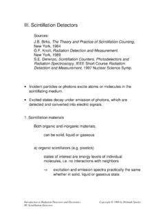
4 The equivalent input Noise voltage decreases as the device width is increased, but only with 1/ W, so the increase in capacitance overrides, decreasing and constCgim=2det02202det222211414)()/( + = +== iiimBsBmisnsCCCCgTkfQNSfTkgCCQvCQNSI ntroduction to radiation Detectors and ElectronicsCopyright 1998 by Helmuth Noise in TransistorsMinimum Obtainable Noise ChargeDevice scaling can be used to determine the minimum obtainablenoise charge for a given device transconductance of an FET increases with drain current asshown , Noise only decreases up to a certain current. The reason isthat the Noise from parasitic source and gate resistances that a transistor of width W assumes its minimum Noise at acurrent Id with an associated transconductance the parasitic gate and source resistances are both inverselyproportional to device width, the current density Id /W will be thesame for all widths of Transistors using the same technology (anddevice length).
5 MOSFET Transconductance vs. Drain Current - W= 100 m, L= m02468100123456 Drain Current [mA]Transconductance [mS] introduction to radiation Detectors and ElectronicsCopyright 1998 by Helmuth Noise in TransistorsThus, to obtain minimum Noise one can tailor the FET to a givendetector by scaling the device width and keeping the current densityId /W this framework one can characterize the device technology bythe normalized transconductance and input capacitanceand use these quantities to scale to any other device width. Since theequivalent input Noise voltagethe normalized input Noise voltage isUsing these quantities the equivalent Noise charge can be written aswhere Cs is any stray capacitance present at the input in addition tothe detector capacitance Cd and the FET capacitance WCi .WCCW ggiimm=='' and mngv12 Wvvnn='202)'('4isdvmnBnWCCCTFWgTkQ++= introduction to radiation Detectors and ElectronicsCopyright 1998 by Helmuth Noise in TransistorsFor WCi = Cd+Cs the Noise attains its minimum valuewhereis a figure of merit for the Noise performance of the :CMOS transistor with m channel lengthAt Id /W= A/m gm /Ci= s-1 and n= a CR-RC shaper with a 20 ns shaping time andan external capacitanceCd+Cs= pFQn,min= 88 aC = 546 electrons,achieved at a device width W= 5 mm, and adrain current of obtainable Noise improves with the inverse square root of theshaping time, up to the point where 1/f Noise becomes significant.
6 Forexample, at T= 1 sQn,min= aC = 11 electrons,although in practice additional Noise contributions will increase theobtainable Noise beyond this value.)(160min,sdvnBnCCTFTkQ+= inmnCg introduction to radiation Detectors and ElectronicsCopyright 1998 by Helmuth Noise in TransistorsMeasured values of the Noise coefficient n for various n- andp-MOSFETs of various geometries for three normalized draincurrents Id /W= /W= /W= channel n-MOSFETs tend to have higher Noise coefficientsat short channel lengths, probably due to increased electrontemperature at high table also shows the Noise degradation after they are majority carrier devices , MOSFETs are insensitive todisplacement damage, but they are affected by ionization damage,which leads to charge buildup in the oxide and the formation ofinterface Spieler, introduction to radiation - resistant Semiconductor Devicesand Circuits, tutorial, in Lumpkin, Eyberger (eds.)
7 BeamInstrumentation, Proceedings of the Seventh Workshop, AIP ConferenceProceedings 390, American Institute of Physics, Woodbury, NY, 1997,ISBN 1-56396-612-3and to radiation Detectors and ElectronicsCopyright 1998 by Helmuth Noise in TransistorsThe preceding discussion has neglected 1/f Noise , which adds aconstant contribution independent of shaping timeAlthough excess low frequency Noise is determined primarily by theconcentration of unwanted impurities and other defects, their Effect ina specific technology is also affected by device size. For some formsof 1/f noise2gffCWLKA =where Cg is the gate-channel capacitance per unit area, and Kf is anempirical constant that is device and process values of the Noise constant for various device types:p-MOSFETKf 10-32 C2/cm2n-MOSFETKf C2/cm2 JFETKf 10-33 C2/cm2 Specific implementations can improve on these should note that this model is not universally applicable, sinceexcess Noise usually does not exhibit a pure 1/f dependence;especially in PMOS devices one often finds several slopes.
8 Inpractice, one must test the applicability of this parameterization bycomparing it with data before applying it to scaled , as a general rule, devices with larger gate area to exhibit better "1/f " Noise introduction to radiation Detectors and ElectronicsCopyright 1998 by Helmuth Noise in Transistorsb) Noise in Bipolar TransistorsIn bipolar Transistors the shot Noise from the base current basic Noise model is the same as shown before, but themagnitude of the input Noise current is much greater, as the basecurrent will be 1 100 A rather than <100 base current Noise is shot Noise associated with the componentof the emitter current provided by the Noise current in the collector is the shot Noise originating in thebase-emitter junction associated with the collector component of theemitter the same argument as in the analysis of the FET, theoutput Noise current is equivalent to an equivalent Noise voltageBenbIqi22=CencIqi22=CeBBCeCemncnI qTkTkIqIqgiv22222)(2)
9 /(2===ECBE nbinciIntroduction to radiation Detectors and ElectronicsCopyright 1998 by Helmuth Noise in Transistorsyielding the Noise equivalent circuitwhere in is the base current shot Noise equivalent Noise chargeSince IB= IC / DCThe current Noise term increases with IC, whereas the second(voltage) Noise term decreases with the Noise attains a minimumat a collector currentECEinvnvnigmBinvnvnigmTFCIqTkTFIq TFCvTFiQvtotCeBiBevininn222222)(22+=+=TF CIqTkTFIqQvtotCeBiDCCen222)(22+= viDCtotBnFFCTkQ 42min,=TFFCqTkIivDCtoteBC1 = introduction to radiation Detectors and ElectronicsCopyright 1998 by Helmuth Noise in TransistorsFor a given shaper, the minimum obtainable Noise is determined onlyby the total capacitance at the input and the DC current gain of thetransistor, not by the shaping shaping time only determines the current at which this minimumnoise is obtainedBJT Noise vs. Collector CurrentCtot= 15 pF, T= 25 ns, Fi= , Fv= Current [ A]Equivalent Noise Charge [el]Base Current NoiseCollector CurrentNoiseIntroduction to radiation Detectors and ElectronicsCopyright 1998 by Helmuth Noise in TransistorsT= 100 nsT= 10 nsBJT Noise vs.)
10 Collector CurrentCtot= 15 pF, T= 100 ns, Fi= , Fv= Current [ A]Equivalent Noise Charge [el]Base Current NoiseCollector CurrentNoiseBJT Noise vs. Collector CurrentCtot= 15 pF, T= 10 ns, Fi= , Fv= Current [ A]Equivalent Noise Charge [el]Base Current NoiseCollector CurrentNoiseIntroduction to radiation Detectors and ElectronicsCopyright 1998 by Helmuth Noise in TransistorsIncreasing the capacitance at the input shifts the collector currentnoise curve upwards, so the Noise increases and the minimum shiftsto higher Noise vs. Collector CurrentCtot= 10 pF, T= 25 ns, Fi= , Fv= Current [ A]Equivalent Noise Charge [el]Base Current NoiseCollector CurrentNoiseBJT Noise vs. Collector CurrentCtot= 50 pF, T= 25 ns, Fi= , Fv= Current [ A]Equivalent Noise Charge [el]Base Current NoiseCollector CurrentNoiseIntroduction to radiation Detectors and ElectronicsCopyright 1998 by Helmuth Noise in TransistorsFor a CR-RC shaper4min,772 DCtotnCpFelQ = obtained at DCtotcCpFnsAI = 26 Since typically DC 100, these expressions allow a quick and simpleestimate of the Noise obtainable with a bipolar that specific shapers can be optimized to minimize either thecurrent or the voltage Noise contribution, so both the minimumobtainable Noise and the optimum current will be change withrespect to the above to radiation Detectors and ElectronicsCopyright 1998 by Helmuth Noise in TransistorsThe Noise characteristics of bipolar Transistors differ from Field effecttransistors in four important equivalent input Noise current cannot be neglected.