Transcription of Vishay Foil Resistors - Performance through Precision
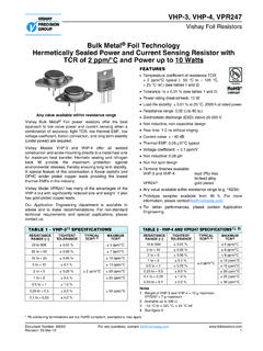
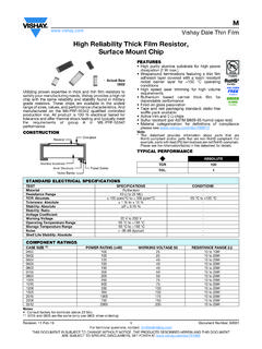
1 High Precision Bulk Metal foil Molded Surface Mount Resistorwith TCR down to 2 ppm/ C, Flexible Terminations,and Load Life Stability of % (50 ppm)SMR1D/SMR3 DVishay foil Resistors Document Number: 63102 For any questions, contact: 23-Mar-101 Any value at any tolerance available within resistance rangeINTRODUCTIONThe SMRxD is a Precision molded surface mountableresistor offering all the elements of Precision ; including lowTCR, tight tolerance, long term stability, low noise, lowthermal EMF, and non-measurable voltage coefficient.
2 Itutilizes the Bulk Metal foil technology for the resistiveelement with its inherent low and predictable TCR and longterm stability. This surface mountable product affords similarperformance to the time tested S series molded flexible terminations of this product also reducestress transference from the PCB to the division with tight tracking < 3 ppm/ C can beachieved with 2 randomly selected units even with a largeratio between the two Application Engineering Department is available toadvise and make recommendations.
3 For non-standardtechnical requirements and special applications, pleasecontact Tighter performances are availableFEATURES Temperature coefficient of resistance (TCR): 2 ppm C typical (- 55 C to + 125 C,+ 25 C ref.) Tolerance: to % Flexible terminations ensure minimal stresstransference from the PCB due to a differencein thermal coefficient of expansions (TCE) Electrostatic discharge (ESD) above 25 000 V Load life stability: % (70 C, 2000 h at rated power) Resistance range: 5 to 80 k (for higher and lowervalues, please contact us) Power rating: to 600 mW at 70 C Non inductive, non capacitive design Current noise: - 40 dB Voltage coefficient: < ppm/V Non inductive: < H Non hot spot design Terminal finishes available.
4 Lead (Pb)-freetin/lead alloy Matched sets with TCR tracking are available upon request Any value available within resistance range ( 1K234) Prototype samples available from 48 h. For moreinformation, please contact For better performances please review SMRxDZ datasheetAPPLICATIONS Military, airborne and space Precision amplifiers High Precision instrumentation Medical Automatic test equipment (ATE) Industrial Audio (high end stereo equipment) EB application Pulse application Measurement instrumentation * Pb containing terminations are not RoHS compliant, exemptions may applyTABLE 1 - THE SMRxD SERIES IS LISTEDIN THE FOLLOWING DSCCSPECIFICATIONSMODELDSCCMIL SPECSMR1D06020 MIL-PRF-55182 SMR3D06021 MIL-PRF-55182 TABLE 2 - TOLERANCE AND TCR VERSUS RESISTANCE VALUE(- 55 C to + 125 C, + 25 C ref.)
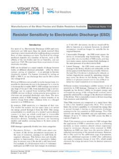
5 VALUESTANDARD TOLERANCE1)TYPICAL TCR AND MAX. SPREAD1)(ppm/ C)50 to 80 k % 2 320 to < 50 % 2 410 to < 20 % 2 65 to < 10 % 2 8 FIGURE 1 - POWER DERATING CURVER1R2 VinVout-+SMRxD2001751501251007550250- 75- 25+ 25+ 75+ 125+ 175 Ambient Temperature ( C)Percent of Rated Power (%)- 55 C+ 70 CSMR1D/SMR3 DVishay foil Resistors any questions, contact: Number: 631022 Revision: 23-Mar-10 Note1. As shown + to allow for measurement error at low valuesTABLE 3 - Performance SPECIFICATIONSTESTCONDITIONSMAXIMUM LIMIT1)SMR1 DSMR3 DSMR1 DSMR3 DResistance Range5 to 33 k 5 to 80 k Rated Power5 to 10 k W at 70 W at 125 C10 k to 33 k W at 70 W at 125 C5 to 30 k W at 70 W at 125 C30 k to 80 k W at 70 W at 125 Csee figure 1 Maximum Working Voltage73 V180 VMaximum Operating Temperature+ 175 C (see figure 1)Working Temperature Range- 55 C to + 125 C (MIL range)Thermal Shock- 65 C to + 150 C; 30 min.
6 5 cycles % (100 ppm)Short Time x rated power; 5 s % (100 ppm)Low Temperature Storage24 h at - 65 C % (100 ppm)Low Temperature Operation45 min, rated power at - 65 C % (100 ppm)Dielectric Withstanding Vo l t ag eatmospheric pressure; AC 200 V; 1 min % (100 ppm)Insulation Resistance (M )DC 100 V; 1 minover 10 000 Resistance toSoldering Heat (%)260 C; 10 s %, % typicalMoisture Resistance+ 65 C to - 10 C; 90 % to 98 % RH; rated power; 240 h % (200 ppm)Shock100 G; sawtooth % (100 ppm)Vibration, High Frequency10 ~ 2000 ~ 10 Hz; 20 G; Y, Z each 4 h % (100 ppm)Load Life Stability (2000 h) W at + 70 W at + 70 W at + 125 W at + 70 W at + 70 W at + 125 CTy p i c a % % %Ty p i c a % % %High Temperature Exposure175 C.
7 No load 2000 h % (500 ppm) gPackagingbulk (loose) or tape and reel, per EIA-481-1 SMR1D/SMR3 DVishay foil Resistors Document Number: 63102 For any questions, contact: 23-Mar-103 FIGURE 2 - DIMENSIONS in inches (millimeters)MODELLWHPTWTH (minimum) ( ) ( ) ( ) ( ) ( ) ( ) ( ) ( ) ( ) ( ) ( ) ( )TH MinimumSide ViewStand OffWBottom ViewLPPEnd ViewHTWTop View100R0T(DATE CODE) -VTOLERANCELEAD (Pb)-FREE INDICATORVALUE (5 DIGITS)FIGURE 3 - RECOMMENDED MOUNTING PAD GEOMETRIES in inches (millimeters)MODELMETHODA REFC REFD ( )E ( ) ( ) ( ) ( ) ( ) ( ) ( ) ( ) ( ) ( )Per IPC-SM-782 Rev.
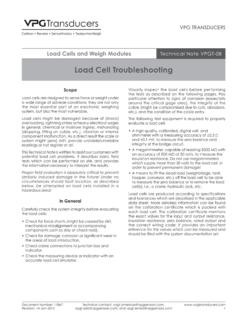
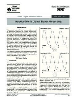
8 AEACBDR eflow Solder PadsFIGURE 4 - TRIMMING TO VALUES (conceptual illustration)Mutual InductanceReduction dueto Change inCurrent DirectionCurrent PathBefore TrimmingTrimming ProcessRemoves this Materialfrom Shorting Strip AreaChanging Current Pathand IncreasingResistanceNOTE: foil shown in black, etched spaces in whiteCurrent PathAfter TrimmingInterloop CapacitanceReduction in SeriesFIGURE 5 - TYPICAL TCR CURVE(for more details, see table 2)Note: The TCR values for < 80 are influenced by thetermination composition and the result in deviation from this curve - 50 - 25 0 + 25 + 50 + 75 + 100 + 125- 55 2 ppm/ C(+ 25 C Reference)+ 150+ 100+ 500 - 50- 100- 150- 200 RR(ppm)Ambient Temperature ( C) SMR1D/SMR3 DVishay foil Resistors any questions, contact: Number: 631024 Revision: 23-Mar-10 Note* For non-standard requests, please contact application 4 - GLOBAL PART NUMBER INFORMATIONNEW GLOBAL PART NUMBER.
9 Y112110K0000T9R (preferred part number format)DENOTES PRECISIONVALUEAER*YR = K = k 0 = standard9 = lead (Pb)-free1 to 999 = customPRODUCT CODERESISTANCE TOLERANCEPACKAGING1121 = SMR1D1169 = SMR3DT= %Q= %A= %B= %C= %D= %F= %L= bulk packR= tape and reelFOR EXAMPLE: ABOVE GLOBAL ORDER Y1121 10K0000 T 9 R:TYPE: SMR1 DVALUE: k ABSOLUTE TOLERANCE: %TERMINATION: lead (Pb)-freePACKAGING: tape and reelHISTORICAL PART NUMBER: SMR1D 10K000 TCR2 T S T (will continue to be used)SMR1D10K000 TCR2 TSTMODELOHMIC k T= %Q= %A= %B= %C= %D= %F= %S= lead (Pb)-freeB= tin/leadB= bulk packT= tape and reel1211K000Y10R0T9 Vishay Precision Group, Disclaimer NoticeDocument No.
10 : 63999 Revision: 15-Jul-2014 DisclaimerALL PRODUCTS, PRODUCT SPECIFICATIONS AND DATA ARE SUBJECT TO CHANGE WITHOUT Precision Group, Inc., its affiliates, agents, and employees, and all persons acting on its or their behalf (collectively, VPG ), disclaim any and all liability for any errors, inaccuracies or incompleteness contained herein or in any other disclosure relating to any product specifications do not expand or otherwise modify VPG s terms and conditions of purchase, including but not limited to, the warranty expressed makes no warranty, representation or guarantee other than as set forth in the terms and conditions of purchase.