Transcription of VS5M ANTI-SHOCK DIRECTIONAL CONTROL VALVES
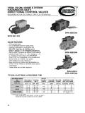
1 FLOW CURVE NUMBERSPOOLSPOOL SHIFTEDSPOOL CENTEREDTYPEPto A or B A or B to T A or B to TP to TA21N/AN/AA2C66N/AN/AB221N/A7F121 8N/AL54N/A31287654321012 345 6 78gpm0102030lpm246810121416bar2252001751 50125100755025psiFLOW P PRESSURE DROPVS5 MANTI-SHOCKDIRECTIONAL CONTROL VALVESSOLENOID ACTUATED, DIRECT OPERATEDDESCRIPTIONAs the valve spool shifts, the spool lands cross overthe valve body ports. This can produce high instantaneous flow rates. The ANTI-SHOCK valve provides a slow spool movement; slower than that ofa standard DIRECTIONAL valve. This results in reductionor elimination of hydraulic system shock produced bythe spool movement and high flow PRESSURE DROP CURVESFLOW PATH PCURVESTYPICAL PERFORMANCE SPECIFICATIONSP erformance is measured on a four-way circuit (fullcircuit). Performance may be reduced from thatshown if a three-way circuit (half circuit) is used, A or B port FLOW RATE5 gpm19 lpm@ 3500 PSIMAXIMUM FLOW RATESEE CHARTMAXIMUMP, A, B Ports4600 psi315 barOPERATINGTPort (includes surges)1500 psi105 barPRESSUREINTERNAL(1-port)9 cipm148 mlpmLEAKAGE3500 psi 100 SUS23 cipm380 mlpmMAXIMUMO ption S160 cpmCYCLEO ption S250 cpmRATE*TIMINGO ption S160 cpmSPOOLO ption S250 cpmSHIFT*MOUNTING - D08 ISO 4401 - SIZE 08 WEIGHTS ingle Actuator31 kgDouble Actuator32 kgSPOOL CODES AVAILABLEA, A2C, B2,F1, SUS75100150 pressure drops shown on this data page arebased on 100 SUS fluid viscosity and specificgravity.
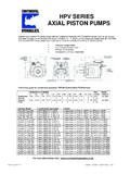
2 See the chart below for other any other specific gravity (G1) the pressure drop( P) will be approximaately P1 = P(G1/G).* Timingfor spool shift is dependent on fluid Certified13VS5 MANTI-SHOCKDIRECTIONAL CONTROL VALVESSOLENOID ACTUATED, DIRECT OPERATEDSPOOL DESCRIPTIONMAXIMUM FLOWCODESYMBOLSPOOL FUNCTIONCENTER POSITION CROSSOVERAA1 CAll ports blockedAll ports blockedA2CB1 All ports open,All ports open,B2restrictedrestrictedPblockedP blockedFA& B restricted A or B restrictedto Tto TLPto TAll ports open,L3A& B blockedrestrictedS1S2AA2CB2F1 LALACDCACDCACDCACDCACDCACDCACDC(23)(23)N /AN/A(19)(23)N/AN/AN/AN/AN/AN/AN/AN/A665 6(27)(27)(15) (23)N/AN/A(23)(30)(23)(23)N/A(23)N/A(19) 7746686665(19)(23)N/AN/A(19)(23)N/AN/AN/ AN/AN/AN/AN/AN/A565 6(23)(23)(15) (19)N/AN/A(19)(30)(19)(15)N/A(23)N/A(15) 66455*85464(15)(23)N/AN/A(19)(23)N/AN/AN /AN/AN/AN/AN/AN/A465 6(19)(19)(15) (15)N/AN/A(15)(30)(15)(12)N/A(19)N/A(12)
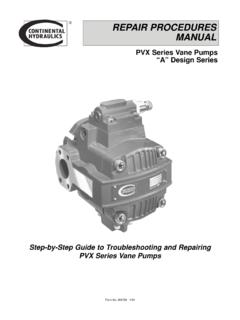
3 55444*84353 SPOOL AND TIMING CODEFUNCTIONCODE(lpm)(70 bar)1@gpm1000 psi3, 5(lpm)(140 bar)1@gpm2000 psi3, 5(lpm)210 bar)1@gpm3000 psi3, 5N/A Valve is not available in this configuration.*95% of rated voltage required at pressure above 2000 TO MOUNTING BOLTS (4)TORQUE USE A5/32 HEX WRENCHTWO LEAD WIRES FOR EACHSOLENOID APPROX. ( ) LONG) CLEARANCEFOR COIL REMOVALHAND TORQUE ONLYFOR SOLENOID NUTDOUBLE SOLENOID AC( ) ( ) ( ) SOL.( ).94( ).08 ORIENTATION PIN( ) DIA. x ( ) LONG .12 .12 OVERRIDE PIN(SOLENOIDENDS ONLY)1/2-14 NPTELECTRICALCONNECTION25 ft. TORQUE( ) ( ) ( ).90( ) MAY BEROTATED 180 Solenoid"b"Solenoid"a"( ) ( ) ( ) ( ).25( ).65( ) SINGLE SOLENOID ACVS5 MANTI-SHOCKDIRECTIONAL CONTROL VALVESSOLENOID ACTUATED, DIRECT OPERATEDTYPICAL ELECTRICAL CHARACTERISTICSDIMENSIONS SHOWN IN: (MILLIMETERS)INCHESNFPA D03 SIZE(Formerly D01)FOR INTERFACE PATTERN,SEE MOUNTING SURFACESECTIONINRUSHVOLTAGE &VOLTAGECURRENT HOLDING HOLDINGSOLENOID CODEFREQUENCYLIMITSRESISTANCE(AMPS)CURRE NTPOWERLEADDINVOLTS - - (AMP)(WATTS) - 60108 - - 5099 - - 60216 - - 50198 - DC21 - DC10 - ( ) b ( ) ( ) ( ) ( ) a ( ) CONTROL VALVESSOLENOID ACTUATED, DIRECT OPERATEDDIMENSIONS SHOWN IN: (MILLIMETERS)INCHESCODES 33L, 34L, 42L & 44 LSolenoid with DIN 43650/ISO 4400 (form A) connector(s).
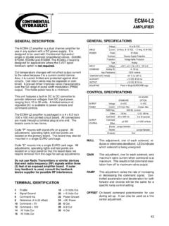
4 NOTE:Top electrical box is :1. No electrical box required2. Order connectors B5 HQuick disconnect for single or double electrical box with sealed 5-pin male :Connector meets ANSI recommended L1 & L2 Solenoid indicator NO. WIRE NO. GOES TO:11 SOL. B22 SOL. A3(GREEN) B16VS5 MANTI-SHOCKDIRECTIONAL CONTROL VALVESSOLENOID ACTUATED, DIRECT OPERATEDORDERING INFORMATIONTYPICAL ORDERING CODE: VS5M-1A-GS1B-60 LVS5M G BASIC VALVE4-WAYDIRECTIONALCONTROLVALVESOLENOI DACTIVATEDD03 SUBPLATEMOUNTING4600 PSIMAXIMUMOPERATINGPRESSURESPOOLSCODEREF ER TOPAGE 13 FOR SPOOLAVAILABILITYSELECTONESELECTONESELEC TONESELECTONESELECTONESELECTONESELECTONE SEALSCODEVITONSEALSSTANDARDCODEOPTIONS15 0 - 150 MSS2**100 - 300 MS(DC Only)TIMING**Timing is dependent on fluid viscosity.** Available on Codes 3 and 5 with DC solenoids actuator 2 positionSpring offset3 Double actuator 3 positionSpring centered5 Single actuator 2 positionSpring centeredFUNCTIONBTbaAPBTbAPBTbaAPCODEDES CRIPTIONOMITNONESINGLESOLENOIDRREVERSEAS SEMBLYSOLENOID A SUPPLIEDWDWASHDOWNMECHANICAL OPTIONSCODEDESCRIPTIONLEAD WIRECONNECTIONSTOPBELECTRICALBOX WITHOUTTERMINAL POSTSTOPELECTRICALBTBOX WITHTERMINALS AND GROUNDTOPELECTRICALBOX WITHB5H5 PIN MALERECEPTACLEFOR 1 OR 2 SOLENOIDSELECTRICAL OPTIONSCODEDESCRIPTIONLEAD WIRECONNECTIONSOMITNOTREQUIREDSINGLESOLE NOIDINDICATORL1110/120 V50/60 Hz12 VDC24 VDCDOUBLESOLENOIDINDICATORL2110/120 V50/60 Hz12 VDC24 VDCSOLENOID INDICATORLIGHTSCODEVOLTAGELEAD WIRECONNECTIONS60L110/120 V50/60 Hz61L220/240 V50/60 Hz70L24 VDC75L12 VDCSOLENOID(S) WITH DIN43650/ISO 4400 (FORM A)
5 CONNECTIONS33L110/120 V50/60 Hz34L220/240 V50/60 Hz42L24 VDC44L12 VDCSOLENOID**Available on Codes 3 and 5with DC solenoids only.