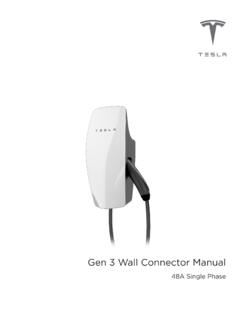
Transcription of Wall Connector, 32A Three Phase Installation Manual
1 WALL CONNECTOR, 32A Three Phase . Installation Manual . Approved Markets: Europe, China, Hong Kong, Australia. For additional languages, please visit: Contents Connect the Set the Operating 19. Secure the Cover and Power 20. About this Product 2. Errors or Copyrights and 2 21. Questions?.. 25. Safety Important Safety 3. Appendix A: Testing for 3 Proper 26. 5 Appendix B: Optional Connection for Load Daisy Chaining Multiple Wall Example of the Communication Optional Circuit 6. Self-Monitoring and Power Appendix C: SRRC (China Load only).. 29. Planning Your 7 Charging Equipment Minimum 7. Service 7 Limited 30. 400V Three - Phase With General 30. 230V Single- Phase With Limits of 230V Single- Phase Without Warranty Enforcement Laws and 230V Three - Phase Without Dispute 31. Determine the Circuit Breaker Country-Specific Consumer 32. Choose the Best Location for the Wall 8.
2 Installation 9. Check the Box 11. Step-by-Step Installation 13. Tools and Materials 13. Overview of Installation 13. Install the Low Profile Bracket for Rear or Bottom Entry 14. Install the Top Entry Bracket for Top Entry Prepare for 16. About this Manual Product Specifications All other trademarks contained in this document are the property of their respective owners and their use herein does not imply All specifications and descriptions contained sponsorship or endorsement of their products in this document are verified to be accurate at or services. The unauthorized use of any the time of printing. However, because trademark displayed in this document or on continuous improvement is a goal at Tesla, we the vehicle is strictly prohibited. reserve the right to make product modifications at any time. Errors or Inaccuracies To communicate any inaccuracies or omissions, or to provide general feedback or suggestions regarding the quality of this Manual , send an email to: Copyrights and Trademarks All information in this document is subject to copyright and other intellectual property rights of Tesla Motors, Inc.
3 And its licensors. This material may not be modified, reproduced or copied, in whole or in part, without the prior written permission of Tesla Motors, Inc. and its licensors. Additional information is available upon request. The following are trademarks or registered trademarks of Tesla Motors, Inc. in the United States and other countries: 2. Safety Information Important Safety Instructions Warning: Do not touch the Wall Connector's end terminals with fingers or sharp metallic objects, such as wire, tools, This document contains important instructions or needles. and warnings that must be followed when installing and maintaining the Wall Connector. Warning: Do not forcefully fold or apply pressure to any part of the Wall Connector or damage it with sharp Warnings objects. Warning: Do not insert foreign objects Warning: Read all the instructions before into any part of the Wall Connector.
4 Using this product. Warning: Use of the Wall Connector may Warning: This device should be affect or impair the operation of any supervised when used around children. medical or implantable electronic devices, such as an implantable cardiac Warning: The Wall Connector must be pacemaker or an implantable cardioverter grounded through a permanent wiring defibrillator. Check with your electronic system or an equipment grounding device manufacturer concerning the conductor. effects that charging may have on such Warning: Do not install or use the Wall electronic devices before using the Wall Connector near flammable, explosive, Connector. harsh, or combustible materials, chemicals, or vapors. Cautions Warning: Turn off input power at the circuit breaker before installing or cleaning the Wall Connector. Caution: Do not use private power generators as a power source for Warning: Use the Wall Connector only charging.
5 Within the specified operating parameters. Caution: Incorrect Installation and testing of the Wall Connector could potentially Warning: Never spray water or any other damage either the vehicle's Battery liquid directly at the wall mounted control and/or the Wall Connector itself. Any box. Never spray any liquid onto the resulting damage is excluded from the charge handle or submerge the charge New Vehicle Limited Warranty and the handle in liquid. Store the charge handle Charging Equipment Limited Warranty. in the dock to prevent unnecessary exposure to contamination or moisture. Caution: Do not operate the Wall Connector in temperatures outside its Warning: Stop using and do not use the operating range of -30 C to +50 C. Wall Connector if it is defective, appears cracked, frayed, broken, or otherwise damaged, or fails to operate.
6 Warning: Do not attempt to disassemble, repair, tamper with, or modify the Wall Connector. The Wall Connector is not user serviceable. Contact Tesla for any repairs or modification. Warning: When transporting the Wall Connector, handle with care. Do not subject it to strong force or impact or pull, twist, tangle, drag, or step on the Wall Connector, to prevent damage to it or any components. Safety Information 3. Safety Information Notes Note: Ensure that the Wall Connector's charging cable is positioned so it will not be stepped on, driven over, tripped on, or subjected to damage or stress. Note: Do not use cleaning solvents to clean any of the Wall Connector's components. The outside of the Wall Connector, the charging cable, and the connector end of the charging cable should be periodically wiped with a clean, dry cloth to remove accumulation of dirt and dust.
7 Note: Be careful not to damage the circuit boards or components during Installation . Note: Use a cable sheath or similar containment to cover the supply cables. The color black is recommended. 4. Specifications The maximum power rating for the Wall Connector is 22 kW or 32A at 400V AC Three - Phase power. Note: Downloadable versions of this publication and an Installation video in languages other than English are available on the Tesla website: Description Specifications Voltage and Wiring Nominal voltage: 230V AC single- Phase : L1, neutral, and earth ground 230V AC Three - Phase : L1, L2, L3 and earth ground 400V AC Three - Phase : L1, L2, L3, neutral and earth ground Voltage range: 180V to 264V AC between N and L1 terminals Current Maximum 32A. Frequency 50 Hz Cable Length m (standard) and m (option). Wall Connector Dimensions Height: 380 mm Width: 160 mm Depth: 140 mm Top Entry Bracket Dimensions Height: 275 mm Width: 130 mm Depth: 50 mm Weight (including bracket) 9 kg Operating Temperature -30 C to 50 C.
8 Storage Temperature -40 C to 85 C. Enclosure Rating IP 55: indoor and outdoor use Agency Approvals CE. Specifications 5. Features Optional Circuit Ratings Power Outages Use a Three - Phase circuit breaker rated for If a power outage occurs, the Wall Connector 32A per Phase to obtain the fastest charging. automatically resumes charging when power In certain Installation locations, this level of is restored. If the charging cable is plugged power isn't readily available. Therefore, you into the vehicle when power is restored, the can adjust the circuit breaker rating on the lights blink and the unit does not energize the Wall Connector from 6A to 32A (refer to Set charging cable for approximately 15 seconds the Operating Current on page 19). to Three minutes. This prevents the utility grid from experiencing a large surge when power is Note: Tesla vehicles must be configured with restored and allows vehicles to begin drawing optional onboard charging equipment to current at random times, rather than all at accept higher amperages.
9 Contact Tesla if you once. have questions about the onboard charging capabilities of your vehicle. Load Sharing Self-Monitoring and Recovery The Wall Connector provides the capability to wire 4 Wall Connectors to a single circuit, The Wall Connector has a ground monitoring giving vehicle owners reassurance that they circuit that continuously checks for the can charge multiple vehicles at home (refer to presence of a safe ground connection and Appendix B: Optional Connection for Load automatically recovers from faults. Manual Sharing on page 27). testing and resetting is not required. Temporary problems such as ground faults or utility power surges are overcome automatically. If a residual current fault occurs that interrupts charging, the Wall Connector automatically tries to clear the fault and re- attempt charging. If the problem is immediately sensed a second time, the Wall Connector waits 15 minutes before trying to charge.
10 This process repeats 4. times and if all attempts are unsuccessful, power is removed and no further attempts are made. In this case, you will see a red error light on the front panel (refer to Troubleshooting on page 21). It is recommended that when you see a red error light, you power off the Wall Connector by switching off the upstream circuit breaker, and then power it back on again. The Wall Connector can alternatively be reset when a red error light is encountered using the RESET button (refer to Reset on page 24). 6. Planning Your Installation Minimum Requirements 230V Single- Phase With Neutral Installation of the Wall Connector requires that For single- Phase use of a Wye-connected you: secondary, only a single- Phase (L1) and neutral should be connected. This Phase voltage Calculate the existing electrical load to should measure 230V between line and determine the maximum operating neutral.