Transcription of WALL CONNECTOR, 80A SINGLE PHASE INSTALLATION …
1 wall connector , 80a single phase installation MANUALTHIS MANUAL IS OF THE HIGHEST IMPORTANCEA pproved Markets: North America, Japan About this or and 2 Safety Safety Circuit 6 Self-Monitoring and Your 7 Minimum 7 Service 7120V Above 7 Ground 7240V 7208V 3- PHASE 8240V Three- PHASE 8277V Three- PHASE the Circuit the Best Location for the 11 Check the Box 13 Step-by-Step 15 Tools and Materials 15 Overview of INSTALLATION 15 Install the Low Profile Bracket for Rearor Bottom Entry 16 Install the Top Entry Bracket for TopEntry for 18 Connect the the Operating the Cover and Power 27 Appendix A: Testing forProper B: OptionalConnection for Load 29 Daisy Chaining Multiple Wall 29 Example of the Communication 30 Charging EquipmentLimited 31 Limits of Enforcement Laws andDispute 32 ContentsCommunications RegulationsThis device complies with Part 15 of the FCCrules and Industry Canada license-exempt RSSstandard(s).
2 Operation is subject to thefollowing two conditions: (1) This device maynot cause harmful interference and (2) thisdevice must accept any interference received,including interference that may causeundesired : Changes or modifications tothis product not authorized by Teslacould void the FCC or InaccuraciesTo communicate any inaccuracies oromissions, or to provide general feedback orsuggestions regarding the quality of thismanual, send an email and TrademarksAll information in this document is subject tocopyright and other intellectual propertyrights of Tesla Motors, Inc. and its material may not be modified,reproduced or copied, in whole or in part,without the prior written permission of TeslaMotors, Inc. and its licensors. Additionalinformation is available upon request. Thefollowing are trademarks or registeredtrademarks of Tesla Motors, Inc.
3 In the UnitedStates and other countries:All other trademarks contained in thisdocument are the property of their respectiveowners and their use herein does not implysponsorship or endorsement of their productsor services. The unauthorized use of anytrademark displayed in this document or onthe vehicle is strictly this Manual2 Important Safety InstructionsThis document contains important instructionsand warnings that must be followed wheninstalling and maintaining the Wall : Read all the instructions beforeusing this : This device should besupervised when used around : The wall connector must begrounded through a permanent wiringsystem or an equipment : Do not install or use the WallConnector near flammable, explosive,harsh, or combustible materials,chemicals, or : Turn off input power at thecircuit breaker before installing orcleaning the Wall : Use the wall connector onlywithin the specified : Never spray water or any otherliquid directly at the wall mounted controlbox.
4 Never spray any liquid onto thecharge handle or submerge the chargehandle in liquid. Store the charge handlein the dock to prevent unnecessaryexposure to contamination or : Stop using and do not use theWall Connector if it is defective, appearscracked, frayed, broken, or otherwisedamaged, or fails to : Do not attempt to disassemble,repair, tamper with, or modify the WallConnector. The wall connector is not userserviceable. Contact Tesla for any repairsor : When transporting the WallConnector, handle with care. Do notsubject it to strong force or impact orpull, twist, tangle, drag, or step on theWall Connector, to prevent damage to itor any : Do not touch the WallConnector s end terminals with fingers orsharp metallic objects, such as wire, tools,or : Do not forcefully fold or applypressure to any part of the WallConnector or damage it with : Do not insert foreign objectsinto any part of the Wall : Use of the wall connector mayaffect or impair the operation of anymedical or implantable electronic devices,such as an implantable cardiacpacemaker or an implantable cardioverterdefibrillator.
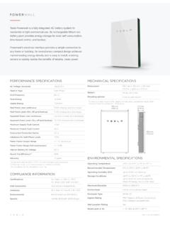
5 Check with your electronicdevice manufacturer concerning theeffects that charging may have on suchelectronic devices before using the : Do not use private powergenerators as a power source : Incorrect INSTALLATION and testingof the wall connector could potentiallydamage either the vehicle s Batteryand/or the wall connector itself. Anyresulting damage is excluded from theNew Vehicle Limited Warranty and theCharging Equipment Limited : Do not operate the WallConnector in temperatures outside itsoperating range of -22 F to 122 F (-30 Cto +50 C).Safety InformationSafety Information3 NotesNote: Ensure that the wall connector scharging cable is positioned so it will not bestepped on, driven over, tripped on, orsubjected to damage or : Do not use cleaning solvents to cleanany of the wall connector s components. Theoutside of the wall connector , the chargingcable, and the connector end of the chargingcable should be periodically wiped with aclean, dry cloth to remove accumulation ofdirt and : Be careful not to damage the circuitboards or components during Information4 The maximum power rating for the wall connector is 20 kW or 80A at 250V AC SINGLE -phasepower.
6 Your vehicle can charge from 200V to 277V SINGLE - PHASE and Wiring277V AC SINGLE - PHASE : L1, neutral, and earth208V or 240V AC SINGLE - PHASE : L1, L2, and earthCurrentMaximum output: 80A, 72A, 64A, 56A, 48A, 40A, 36A,32A, 28A, 24A, 20A, 16A, 12 AFrequency50 to 60 HzCable ' ( m) and 24' ( m) wall connector DimensionsHeight: " (380 mm)Width: " (160 mm)Depth: " (140 mm)Top Entry Bracket DimensionsHeight: " (275 mm)Width: " (130 mm)Depth: " (50 mm)Weight (including bracket)20 lb (9 kg)Operating Temperature-22 C to 122 C (-30 C to 50 C)Storage Temperature-40 F to 185 F (-40 C to 85 C)Enclosure RatingType 3 RAgency ApprovalscULus listed for United States and Canada under filenumber E354307, FCC Part Circuit RatingsUse a SINGLE - PHASE circuit breaker rated for100A per PHASE to obtain the fastest certain INSTALLATION locations, this level ofpower isn t readily available.
7 Therefore, youcan adjust the circuit breaker rating on theWall Connector from 15A to 100A (refer to Setthe Operating Current on page 21).Note: Tesla vehicles must be configured withoptional onboard charging equipment toaccept higher amperages. Contact Tesla if youhave questions about the onboard chargingcapabilities of your and RecoveryThe wall connector has a ground monitoringcircuit that continuously checks for thepresence of a safe ground connection andautomatically recovers from faults. Manualtesting and resetting is not problems such as ground faults orutility power surges are overcomeautomatically. If a residual current fault occursthat interrupts charging, the Wall Connectorautomatically tries to clear the fault and re-attempt the problem is immediately sensed a secondtime, the wall connector waits 15 minutesbefore trying to charge.
8 This process repeats 4times and if all attempts are unsuccessful,power is removed and no further attempts aremade. In this case, you will see a red error lighton the front panel (refer to Troubleshootingon page 23). It is recommended that whenyou see a red error light, you power off theWall Connector by switching off the upstreamcircuit breaker, and then power it back wall connector can alternatively be resetwhen a red error light is encountered usingthe RESET button (refer to Reset on page26).Power OutagesIf a power outage occurs, the Wall Connectorautomatically resumes charging when poweris restored. If the charging cable is pluggedinto the vehicle when power is restored, thelights blink and the unit does not energize thecharging cable for approximately 15 secondsto three minutes. This prevents the utility gridfrom experiencing a large surge when power isrestored and allows vehicles to begin drawingcurrent at random times, rather than all SharingThe wall connector provides the capability towire 4 Wall connectors to a SINGLE circuit,giving vehicle owners reassurance that theycan charge multiple vehicles at home (refer to Appendix B: Optional Connection for LoadSharing on page 29).
9 Features6 Minimum RequirementsInstallation of the wall connector requires thatyou: Calculate the existing electrical load todetermine the maximum operatingcurrent. Calculate the distance to ensure minimalvoltage drop. Obtain any necessary permits from thelocal authority that has jurisdiction andconfirm that the follow-up inspection hasbeen scheduled by an electrician after theinstallation is complete. Use only copper conductors. Use conductors that are sized inaccordance with local wiring selected cable must be able to sustainperiods of constant load of up to 80A. Use protective devices. The circuitprotection device chosen mustincorporate a suitable residual-currentdevice (RCD) and overcurrent protectionin relation to the electrical load : Consult with an electrician to ensurethat the INSTALLATION meets local Wiring120V Above GroundWarning: The wall connector is a SINGLE - PHASE device.
10 Do not connect all threephases of a three- PHASE : Before installing the WallConnector, identify the type of utilityservice connection available on site. If youare unsure about the type of connectionavailable at the service panel, consult anelectrician, or contact Tesla for : The two phases used must eachmeasure 120V to neutral. Earth groundmust be connected to neutral at only onepoint, usually at the breaker : If a 240V three- PHASE feed isfrom a Delta-connected secondary, theleg used must have a center tap. Thiscenter tap must be grounded. Only thetwo phases on either side of the center-tapped leg can be three wires are connected, but care mustbe taken that the service transformersecondary connection is definitely known, andthat the three wires from the main circuitbreaker panel are correctly connected andlabeled. The illustrations shown are the mostcommonly used wiring : The L1, L2, and ground outputs labeledon the illustrations correspond to the inputson the Wall ConnectionAlways connect the Neutral at the service toEarth Ground.