Transcription of Week 2 8051 Assembly Language Programming Chapter 2
1 1 Week 28051 Assembly Language ProgrammingChapter Inside the Introduction to 8051 Assembly Assembling and running an 8051 The program counter and ROM space in the 8051 data types and 8051 flag bits and the PSW 8051 register banks and stack3 Inside the 8051 On-chip ROMto save your program Program is burned in ROM. Program is fixed and is not supposed to change. On-chip RAMto save some temporary data generated in execution time Data can be changed. Data is lost when the 8051 powers down. Registers to store information temporarily Some registers are used for internal operations of the 8051. Some registers are located in RAM. Some have their special RAM58051 Registers Registers are used to store information temporarily. The 8051 has 8-bit registers and 16-bit registers. many 8-bit registers in Figure 2-1 (a) two 16-bit registers in Figure 2-1(b)6 Main RegistersR0R4R5R2R1R3R6R7 BAAccumulatorfor all arithmetic and logic instructionsRegisters R0-R7set of general-purpose registersRegister Bhelps Register A for arithmetic/logical operations, ex: MUL, DIV716 bit Registers DPTR: data pointer - the 16-bit address for the data located in program (ROM) or external RAM DPL low byte of DPTR DPH high byte of DPTR PC program counter - the address of the next instruction8 Special Function Registers SFR9 Bit addressable Registers The 8051 uses 8-bit data type.
2 Example: integer and character are 8 bits. Bit-addressable (ex: P0) vs. not bit-addressable (ex: DPH) Any data larger than 8-bits must be broken into 8-bit chunks before it is significant bit (MSB)least significant bit (LSB)Bit-addressable10 Instruction Set SummaryTable A-1: 8051 Instruction Set Summary1. Data Transfer get or store data MOV, PUSH, POP2. Arithmetic Operations ADD, SUB, INC, DEC, MUL, DIV3. Logical Operations ANL, ORL, XRL, CLR4. Program Branching jump, loop, call instruction LCALL, RET, LJMP, JZ, JNZ, NOP11 MOV Instruction Copy the source operand to the destination destination, sourcecopyMOV A,#55H;load value 55H into reg. A;now A=55H (H: hexadecimal) MOV R6,#12 ;load 12 decimalinto R6;now R6=12=0CH MOV R0,A;copy contents of A into R0;now A=55H, R0=55H The pound sign # indicates that it is an immediatevalue. You can write your command after the semicolon ; .12 MOV - more Other examplesMOV R5,#0F9H;load F9H into R5;now R5=F9H A 0 is used between the # and F to indicate that F is a hex number and not a letter.
3 MOV R5,#F9H ;illegal The value must be within 0-0 FFH (or decimal 0-255).MOV R5,#425 ;illegal If no # exists, it means to load from a memory A,17H ;load the value held in memory ;location 17H to reg. A13 MOV - more Other examplesMOV A,# 4 ;load ASCII 4 into A;now A=34H The immediate value can be copied to A, B, Instruction Add the source operand to register A and put the result in A, sourceA + source AMOV A,#25H;load 25H into AMOV R2,#34H;load 34H into R2 ADD A,R2 ;add R2 to A=A+R2;now A=59H, R2=34H Register A must be the destination of any arithmetic R0,A ;illegal15 ADD - more Other examplesMOV A,#25H;load 25H into AADD A,#34H;add 34H to A=A+34H=59H The second value is called an immediate operand. The format for Assembly Language instruction, descriptions of their use, and a listing of legal operand types are provided in Appendix (to be discussed in Chap 5)16 Assembly Language Programming Machine Language a program that consists of 0s and 1 s.
4 CPU can work on machine Language directly. Example 7D25 Low-level Language It deals directly with the internal structure of the CPU. Programmers must know all details of the CPU. Example MOV R5,#25H 8051 Assembly Language High-level Language Machine independent Example a=37;C++17 Assembly Language Programming Assembly languages were developed which provided mnemonics for the machine code instructions, plus other features. Mnemonic: the instruction Example: MOV, ADD Provide decimal numbers, named registers, labels, comments Programming faster and less prone to error. Assembly Language programs must be translated into machine code by a program called an Program 2-1 ORG OH ;start (origin) at ;location 0 MOV R5,#25H ;load 25H into R5 MOV R7,#34H ;load 34H into R7 MOV A,#0 ;load 0 into AADD A,R5 ;add contents of R5 to A;now A = A + R5 ADD A,R7 ;add contents of R7 to A;now A = A + R7 ADD A,#12H ;add to A value 12H;now A = A + 12 HHERE:SJMP HERE ;stay in this loopEND ;end of asm source filedirectivesinstructions19 Assembly Language Programs An Assembly Language program (see Program 2-1) is a series of statements.
5 [label:] mnemonic [operands] [;comment] Brackets indicate that a field is optional. Label is the name to refer to a line of program code. A label referring to an instruction must be followed by a common : . Here: SJMP HERE Mnemonic and operand(s) perform the real work of the program. The comment field begins with a semicolon ; .20 Mnemonic vs Directives Two types of Assembly statements Mnemonictells the CPU what to do ExampleMOV, ADD These instructions are translated into machine code for the CPU to execute. Pseudo-instructiongives directions to the assembler Example ORG 0H, END Pseudo-instructions are calleddirectives, too. Pseudo-instructions do not generate any machine code and are used only by the Directives ORG tells the assembler to place the opcode at ROM with a chosen start address. ORG start-addressORG 0200H;put the following codes ;start at location 200H ORG indicates the address of next instruction to be run.
6 END indicates to the assembler the end of the source ;end of asm source file EQU used for aliasDATA EQU 25H Some assemblers use .ORG and .END22 Steps in Assembly Language an editorto type in a program (may use other extensions) Assembly source program is fed to an 8051 assembler. and are generated by the link programtakes one or more object files to produce an absolute object file . These abs files are used by 8051 trainers that have a monitor abs file is fed into a program called OH (object to hex converter) which creates a file file is to be burned into ROM by a special burner. New Windows-based assemblers combine 2-4 into one step23 Program 2-1 0H ;start at location 0 MOV R5,#25H ;load 25H into R5 MOV R7,#34H ;load 34H into R7 MOV A,#0 ;load 0 into A ADD A,R5 ;add contents of R5 to A ;now A = A + R5 ADD A,R7 ;add contents of R7 to A;now A = A + R7 ADD A,#12H ;add to A value 12H ;now A = A + 12 HHERE:SJMP HERE ;stay in this loopEND ;end of asm source file 0000 ORG 0H ;start at location 02 0000 7D25 MOV R5,#25H ;load 25H into R5 3 0002 7F34 MOV R7,#34H ;load 34H into R7 4 0004 7400 MOV A,#0 ;load 0 into A 5 0006 2D ADD A,R5 ;add contents of R5 to A 6 0007 ;now A = A + R57 0007 2F ADD A,R7 ;add contents of R7 to A8 0008 ;now A = A + R79 0008 2412 ADD A,#12H.
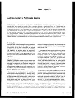
7 Add to A value 12H 10 000A ;now A = A + 12H11 000A 80FE HERE:SJMP HERE ;stay in this loop12 000A END ;end of asm source file 25 ROM ContentsFE000B80000A1200092400082F00072D 00060000057400043400037F00022500017D0000 CodeAddress 26 Linking When we write a large program, we may partition the job into several little programs. These little programs are assembled separately by different programmers. Finally, link them together and produce an absolute program with an absolute Hex File A record looks like :0300300002337A1E Breaking this line into it's components we have: Record Length: 03 (3 bytes of data)Address: 0030 (the 3 bytes will be stored at 0030, 0031, and 0032)Record Type: 00 (normal data)Data:02, 33, 7 AChecksum:1E More than one record is possible Taking all the data bytes above, we have to calculate the checksum based on the following hexidecimal values: 03 + 00 + 30 + 00 + 02 + 33 + 7A = E2 The two's complement of E2 is 1E which is, as you can, the checksum value.
8 For our example:0A0000007D257F3474002D2F24129B28 Program Counter The Program Counter PC points to the address of the nextinstruction to be executed. As the CPU fetches the opcode from the program ROM, the program counter is incremented to point to the next instruction. PC is called instruction pointer, F E D C B A 9 8 7 6 5 4 3 2 1 0 16-bit register0 0 0 0 0 0 0 0 0 0 0 0 0 0 0 0 0000H 0 0 0 0 0 0 0 0 0 0 0 0 0 0 0 1 0001H 0 0 0 0 0 0 0 0 0 0 0 0 0 0 1 0 0002H1 1 1 1 1 1 1 1 1 1 1 1 1 1 1 0 FFFEH 1 1 1 1 1 1 1 1 1 1 1 1 1 1 1 1 FFFFH29 Program counter - more The PC in the 8051 is 16-bits wide. The 8051 can access program addresses 0000 to FFFFH, a total of 64K bytes of code. The exact range of program addresses depends on the size of on-chip ROM.
9 When the 8051 is powered up, the PC has the value of 0000 in it. That is, the address of the first executed opcode at ROM address is 0000H. We can examine the list file to loop the action of Counter - more000 AADD A,#12H24120008 ADD A,R72F0007 ADD A,R52D0006 MOV A,#074000004 MOV R7,#34H7F340002 MOV R5,#25H7D250000 Assembly LanguageMachine LanguageROM AddressORG 0H: put the instruction with the ROM address 0000H2 byte opcodenext instruction is 0+2=0002 Program is from 0000 to 0009. Total 10 bytes. 000A is the address of the next instruction if with 8051 is powered up. The PC is set to the value CPU fetches the instruction with address 0000H and gets the machine code 7D. The CPU decodes it and asks the operand 25. The PC is set to the value CPU fetches the instruction with address 0002H and gets the machine code 7F. The CPU decodes it and asks the operand 34. The PC is set to the value the same work until the 8051 is powered ROM Map The 8051 can access 64K bytes of ROM since the PC is 16-bit register.
10 10000H bytes = 216bytes = 64K bytes 0000 to FFFF address range However, the exact program size depends on the selected chip. 8751, AT8951 have only 4K bytes. AT89C52 has 8K bytes Dallas Semiconductor s DS5000-32 has 32K bytes on-chip 2-3 On-chip ROM address range34 Data Types and Directives The 8051 microcontroller has only one data type. 8-bit data 00 to FFH data range (0 to 255 in decimal) Programmers must take care of the meaning of data type by themselves. Assembly Language defines some data representations and pseudo instructions. DB, EQU Assembler can translate these data representations to be processed by the Byte (DB) Directive Define byte in the DB data-valuedata-value data-nameORG 500H DATA1: DB 28 ;decimal (1C in hex)DATA2: DB 00110101B;binary (35 in hex)DATA3: DB 39H ;hexadecimal data-nameis the label referring to the ROM addresscontaining the content data-value.