Transcription of What is load pull analysis for power amplifiers and …
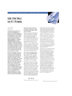
1 Signal Processing Group Inc., technical memorandum onRF is load pull analysis for power amplifiers and how isit done? : load pull analysis is used to construct a set of contours ( typically on aSmith Chart), which determine the maximum power outputachievable with agiven load impedance. These contours are very useful in assessing the actualimpedance a device should see when it is used in an contours are constructed in the following way:The device or amplifier under test (DUT) operates betweentwo impedances,one at the input and one at the output. Between these impedances sittwotuners, an input tuner and an output load pull contoursMax power point- 1 dB- dBSignal Processing Group Inc., technical memorandum onRF function of the input tuner is to adjust the matching such that the largesignal input power is always a constant, even when the output impedanceand the output tuner is the closest match at the output is found for the optimum outputimpedance ( See earlier article about load lines and impedances).
2 This isdone by adjusting both the input and the output tuners to get the maximumconstant output power . This forms the center of the load pulllociand is asingle the output impedances are changed and the input tuner is adjusted toprovide conjugate matching and thus constant input is repeatedas many times as possible and for eachconstant outputpower point, a set ofloci are generated which providethe impedances which provide that are shown on Smith Chart thateach contour represents the maximum output powerachievablewith a given load impedance. load pull contoursare useful in determiningthe actual impedance a device should see when used in an also predictgraphicallywhat will happen when the load changes fromthe optimum load due to any anomalies such as aging and other variationsinthe impedances at the output and is a valuable aid in the design andevaluation of power precautionary step needs to be taken however. load pull tuners canaccurately synthesize a given load impedance; thisimpedanceis only at aknown fundamental frequency.
3 Unfortunately, the harmonic impedances thatresult fromparticular settings of the tuners are usually not harmonic impedances can make a significant difference to the efficiencyof the device, so load pull characterization needs to be carefully interpretedif contours of constant efficiency are measured instead of constant the device is not heavily saturated then the error of changing harmonicterminations between open and short circuits is usually less than a dB or Processing Group Inc., technical memorandum onRF Treatment of load pull analysis can be attempted analytically. It starts by using the theexpression for the load impedance at the internal nodes of the transistor formaximum linear power just at the 1 dB compression = 2 VDD/IMAX( )VDD = Supply voltageIMAX = Maximum currentROL = Optimum load impedance for maximum linear this defines the output power contour for the maximum powerand it becomes a point on the load pullcontours shown the load impedance is less than ROL, then the power becomesdependent on the maximum current swing.
4 This is because when ZL ( theoutput impedance) is smaller than theROL, more current is required togenerate a large voltage swing and hence more power . This is the case ofcurrent limited the load impedance is larger than ROL,then power becomesdependent on the voltage swing of the device since a larger voltage swing isrequired to generate the a large current and hence a large output power . Thisis the case of voltage limited that in each of the above cases the input power is assumed to besufficient to still drive the device to amaximumcurrent or a input power is continuously tuned to keep it thecase of current limited power , the loadimpedance ZL = RL + jXLis being maximum linear power an then be written as:PO = (1/2)IPEAK2*RL( )The peak to peak output voltage is:Signal Processing Group Inc., technical memorandum onRF (VPP) = IMAX*SQRT(RL2 + XL2)( )Using equation ,IMAX = 2 VDD/ROL( )Then,ABS(VPP) = (2 VDD/ROL)*SQRT(RL2 + XL2)( )Now, in case of a current limited amplifier, the voltage swingnever gets tothe maximum 2 VDD, then the following must be true:For ABS(VPP) = 2 VDD,We must have,SQRT(RL2 + XL2) /(ROL) = 1(6)Or,RL2 + XL2= ROL2(7)So for,ABS(VPP) < 2 VDDWe must have,ROL2 = RL2 + XL2Or,ABS(XL2) ROL2- RL2(8)Looking at the voltage limited case, a dual analysis can be done.
5 In this caseit is appropriate to use a parallel admittance,Signal Processing Group Inc., technical memorandum onRF = GL + jB(9)In this case, a dualanalysis yields the maximum linear power ,PO = (1/2)*VPEAK2/ RL= (1/2)(VDD)2*GL(10)In an analogous manner to the development for the current limited case,In the voltage limited case the current never gets to its full output the susceptance must follow the expression given below:ABS(BL) (GOL2 GL2)(11)From these equations one can derive load pull power contours as follows:A: Determine the optimum load impedance ROL from equation (1).This provides the maximum power point ( the center of the load pullcontours)B: Generate the ratio of the given power level PO with respect to optimumpower POPT (as above in A:) Then,PO/POPT = RL/ROL ( forcurrent limited case)OrPO/POPT = GL/GOLFor the voltage limited : Using the ratios of power above determine the resistive points on thecontour of that power level.
6 To clarify this further, if the ratio of the currentlimited case for the power levels is , then RL = This providestheresistive point for starting the construction of the at thesmaller resistancethe contour follows a constant resistanceline on the Smith Chart up to thereactance limits given by equation Processing Group Inc., technical memorandum onRF starting ata higher resistance, the contour follows aconstant conductanceline on the Smith Chart up to the susceptance limits given by equation :Finally move the reference plane from the interior or intrinsic side of thedevice to the external device terminals and includedevice output shuntcapacitance and bondwire parasitics into the then provides a procedure to allow load pull contours to be generatedby hand. The are a number of CAD toolstoday that can do this and if such atool is available by all means it should be used. However, the engineershould know a priori approximately what to expect otherwise the processwill not be a closed one for how does the engineer know if the CAD toolresult is near or accurate?