Transcription of Wheel Bearing Adjustment Procedures TMC RP618 - ConMet
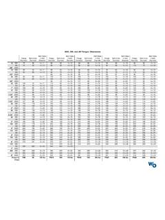
1 Manual Adjust Hub Wheel Bearing Adjustment Procedures TMC RP618 . WARNING: Failure to fill the hub with the correct amount of lubricant can cause premature failure of the ConMet hub assembly, which, if not avoided, could result in death or serious injury. IMPORTANT: Use the proper hubcap for the type of lubricant intended to be used. 1. Lubricate the bearings with clean lubricant of the same type used in the axle sump or hub assembly. 2. Install the Wheel hub and Bearing onto spindle and Torque the inner adjusting nut to 200 ft-lbs while rotating the hub assembly. 3. Back off the inner adjusting nut one full turn. Rotate the hub. 4. Re-torque the inner adjusting nut to 50 ft-lbs while rotating the Wheel hub assembly. 5. Back off the inner Adjustment nuts as per chart below. Axle Type Threads Per Inch Final Back Off 12 1/6 turn* (with cotter pin). 18 1/4 turn* (with cotter pin).
2 Steer (front 12 1/3 turn (with less than 2 5/8 nut). non-drive). 14 1/2 turn (with less than 2 5/8 nut). 18 1/2 turn (with less than 2 5/8 nut). 12 1/4 turn Drive 16 1/4 turn 12 1/4 turn Trailer**. 16 1/4 turn 6. Install the locking washer. 7. Install and torque the outer jam nut as per chart below. Axle Type Nut Size Torque Steer (front No Jam Nut Install Cotter Pin non-drive) Under 2-5/8 200 - 300 ft-lbs Dowel Washer 300 - 400 ft-lbs Drive Tang** washer 200 - 275 ft-lbs Trailer** 2-5/8 and over 200 - 300 ft-lbs 8. Use a dial indicator to verify acceptable endplay of .001 - .005 (NOTE: If end play is not within specification, readjustment is required. Be sure to install or activate any locking device.). * Single Nut ** Positive Adjustment Wheel bearings (a product of Rockwell International), use 250-300 ft-lbs on adjusting nut and jam nut. See Rockwell Field Maintenance Manual No.
3 14. ** For single axle (13,000 - 19,000 lb capacity) with tang washers, consult manufacturer's specifications. This information is intended for reference only. Consolidated Metco does not assume any liability in the event of improper use or mismatch of components. For additional information see ConMet Hub Manual or TMC RP618 . Manual Adjust Hub Torque Specifications Torque Item Measurement Notes (ft-lbs). Ball Seat 3/4 - 16 450 - 500 Always tighten the top nut first or pilot damage may Wheel Nut 1 1/8 - 16 result. Do not lubricate the faces of the hub, drum, Wheel or on the ball seats of the Wheel nuts. The last nut rotation should be with a calibrated torque device. Hub Pilot 22 mm x mm 450 - 500 Always tighten the top nut first or pilot damage may Wheel Nut Apply two drops of oil between the nut and nut flange , and two or three drops to the outermost 2 or 3 thread of the Wheel studs.
4 Lightly lubricate the Wheel pilots on the hub. The last nut rotation should be with a calibrated torque device. Drive 3/4 - 16 40 - 90 Torque value is for drive axle stud installation only. For Studs, 5/8 - 18 40 - 90 drive axle flange nuts, see axle manufacturer's recom- Installation Torque 9/16 - 18 40 - 60 mendations for proper torque. 1/2 - 20 40 - 60. Hub Cap 5/16-18 12 - 18 Minimum SAE Grade 5 fasteners, flat washers only. Oil Fill Plug 1/4 NPT 20 - 25. 3/8 NPT. 9/16 - 18 O-Ring Style Disc Brake Rotor M8 x 18 - 22 - Screw 1/2 - 20 100 - 110. 9/16 - 12 130 - 150. 5/8 - 11 190 - 210. 5/8 - 18 155 - 195. Disc Brake 5/8 - 18 180 - 210 - Rotor Nut Disc Brake Rotor M16 x 190 - 210 - Drive Axle flange See axle manufacturer's recommendations for proper Nuts drive axle nut torque. WARNING: Always tighten the top nut first to fully seat the brake drum on the drum pilot and against the hub face.
5 See the adjacent diagram for bolt tightening sequence, and tighten in order from 1 through 8 or 10, depending on the bolt pattern. Reprints available from: Consolidated Metco, Inc. 5701 SE Columbia Way, Vancouver, WA 98661. Part No. 10036675. 9-2013 Printed in the USA 2013 CONSOLIDATED METCO, INC.