Transcription of Wheelock Series MT Multitone Horns and …
1 Effective: October 2017K-75-001 Wheelock Series MT Multitone Hornsand Multitone horn -StrobesFEATURES Approvals include: UL 1971, UL 1638, UL 464, and Cali-fornia State Fire Marshal (CSFM). The MT-12/24-R andMTWP-2475W-FR are FM approved and also US CoastGuard Approved for applications with the Autroprimefire alarm system Designed to meet or exceed ADA/NFPA/UFC/ANSI Stan-dards and Accessibility Guidelines Meets OSHA 29 Part 1910, 165 One alarm appliance with eight (8) selective signals toprovide superior sound penetration for various ambientand wall conditions with two field selectable sound out-put levels Audible and strobe can operate from a single signalingcircuit with any of the eight (8) audible signals Code-3 horn and Tone meet ANSI/NFPA temporal pat-tern for standard emergency evacuation signaling Multi-Candela MT Strobe models available with fieldselectable 15/30/75/110 candela settings Weatherproof MT Strobe models available with 180 can-dela rating FIRE and AGENT markings available Polarized inputs for compatibility with standard reversepolarity type supervision of circuit wiring by an alarmpanel Flush and surface mount options.
2 No additional trim-plate required for flush mounting IN and OUT wiring terminations that accepttwo (2) #12 to #18 AWG wires at each terminalDESCRIPTIONE aton s Wheelock Series MT Multitone Horns and horn -Strobes are compatible with Kidde Fire Systems'AEGIS and ARIES families of Fire-Alarm Suppres-sion Control Units and offer a choice of eight (8) nation-ally and internationally recognized alerting sounds: horn ,Bell, March Time horn , Code-3 Tone, Code-3 horn , SlowWhoop, Siren or Hi/Lo Tone. The Code-3 horn and tonepatterns are engineered to comply with NFPA/ANSI Tem-poral Pattern specifications without requiring additionalequipment. The MT Strobes are designed for ADA applications withmaximum performance, reliability and cost-effectivenesswhile meeting or exceeding the requirements of NFPA72, ANSI , UFC and UL Standard 1971 as well asmeeting ADA requirements concerning MT and MT Strobe appliance has two user selec-tive sound output levels: STANDARD dBA and HIGHdBA.
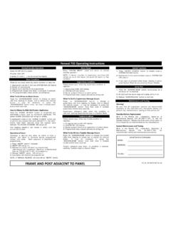
3 The MT-12/24 provides dual voltage capability inone unit, 12 VDC or 24 VDC operation, filtered or MT Strobe Electronic appliances operate with 24 VDC and may be used with filtered or unfiltered (full-wave-rectified) input voltages. Separate input terminalsare available and shunt wires are provided to enable bothtone and strobe to operate simultaneously from a Multitone Strobe appliances are UL Listed for indoorwall mount applications, under Standard 1971 forDevices for the Hearing Impaired and under Standard464 for Audible Signal Appliances. MT Strobe models arelisted for indoor use with a temperature range of 32 F to120 F (0 C to 49 C) and maximum humidity of 93% 2%. Series MT HornSeries MT horn -Strobe with IOB BackboxThe MT-12/24 and MTWP models for outdoor use areListed for -31 F to 150 F (-35 C to 66 C) and maximumhumidity of 95%.
4 The strobe devices use a Xenon flash-tube with solid state circuitry enclosed in a ruggedLexan (or equivalent) lens to provide maximum reliabil-ity for effective visible signaling. Strobe lens markingsavailable for Fire and Agent labeled MT-12/24-R and MTWP-2475W-FR are US CoastGuard Approved for applications with the Autroprime firealarm Series MT appliances have IN and OUT wiring termi-nations that accept two #12 to #18 AWG wires at each terminal. Inputs are polarized for compatibility with stan-dard reverse polarity type 2 -GENERAL NOTES Strobes are designed to flash at 1 flash per second minimum over their Regulated Voltage Range (16-33v for24 VDC units and for 12 VDC units). All candela ratings represent minimum effective Multitone Strobe intensity based on UL 1971. The MT Audible is UL 464 Listed.
5 Regulated Voltage Range is the terminology used by UL to identify the voltage range. Prior to this change, ULused the terminology Listed Voltage Range. SPECIFICATIONST able 3: UL dBA and Current Ratings for Series MT Audible Portion*RMS current ratings are per UL average RMS method. UL max current rating is the maximum RMS current within the listed voltage range (16-33v for 24v units). For strobes the UL max current is usually at the minimum listed voltage (16v for 24v units). For audibles the max current is usually at the maximum listed voltage (33v for 24v units). For unfiltered FWR ratings, see installation neRMS Current (Amps)dBA @ 10 FT (UL Reverberant)per UL 46424 VDC12 VDC24 VDC12 VDCHI OutputSTD OutputHI OutputSTD OutputHI OutputSTD OutputHI OutputSTD Output@ 24 VDCUL max*@ 24 VDCUL max*@ 24 VDCUL max*@ 24 VDCUL max* Time 1: Alarm TonesToneAlarm Tones Pattern DescriptionHornBroadband horn (Continuous)Bell1560 Hz Modulated ( sec ON/Repeat)March Time HornHorn ( sec sec.)
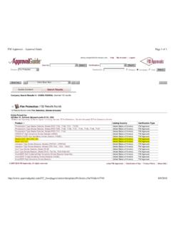
6 OFF/Repeat)Code-3 HornHorn (ANSI Temporal Pattern)Code-3 Tone500 Hz (ANSI Temporal Pattern)Slow Whoop500-1200 Hz SWEEP( sec sec. OFF/Repeat)Siren600-1200 HZ SWEEP ( sec. ON/Repeat)Hi/Lo1000/800 ( sec. ON/Alternate)*RMS current ratings are per UL average RMS method. UL max current rating isthe maximum RMS current within the listed voltage range (16-33v for 24v units). For strobes the UL max current is usually at the minimum listed voltage (16v for 24v units). For audibles the max current is usually at the maximum listed voltage (33v for 24v units). For unfiltered FWR ratings, see installation 2: Current Ratings for Series MT Strobe PortionModelRMS Current (Amps) Max* 3 -WIRING DIAGRAMSINSTALLATION the strobe and audible operate on the same cir-cuit, add the strobe current from Table 2 to the audi-ble current from Table 3.
7 For Peak and Inrushcurrent across the listed voltage range, refer toInstallation average current indicated is per actual Produc-tion Testing at listed VDC. For rated average andPeak current across the UL listed voltage range forboth filtered DC and unfiltered VRMS, see Installa-tion Kidde for Installation Instructions sheetson these products. These materials contain import-ant information that should be read prior to specify-ing or installing these products, including: Total current required by all devices connected tosystem primary and secondary power sources. Fuse ratings on signaling circuits to handle maxi-mum inrush or peak currents from all devices onthose circuits. Composite flash rate from multiple strobes withina person s field of view. Installation in office areas and other specificationand installation issues.
8 Use strobes only on circuits with continuouslyapplied operating voltage. Do not use strobes oncoded or interrupted circuits in which the appliedvoltage is cycled on and off, as the strobe maynot flash. The voltage applied to these products must bewithin their rated input voltage range. Conductor size (AWG), length and ampacityshould be taken into consideration prior to designand installation of these products, particularly inretrofit notification appliances must be used withintheir published specifications and must be PROP-ERLY specified, applied, installed, operated, main-tained and operationally tested in accordance withtheir installation instructions at the time of installa-tion and at least twice a year or more often and inaccordance with local, state and federal codes, reg-ulations and laws.
9 Specification, application, installa-tion, operation, maintenance and testing must beperformed by qualified personnel for proper opera-tion in accordance with all of the latest National FireProtection Association (NFPA), Underwriters Labo-ratories (UL), National Electrical Code (NEC), Occu-pational Safety and Health Administration (OSHA),local, state, county, province, district, federal andother applicable building and fire standards, guide-lines, regulations, laws and codes including, but notlimited to, all appendices and amendments and therequirements of the local Authority Having Jurisdic-tion (AHJ).WARNINGF ailure to comply with the installationinstruction sheets could result in improperinstallation, application, and/or operationof these products in an emergency situa-tion, which could result in property damageand serious injury or death.
10 +++___FROMPRECEDINGAPPLIANCE,SM/DSMOR FACPTO NEXTAPPLIANCEOR EOLRSIGNALMT SIGNALAUDIBLE SIGNAL AND STROBEOPERATE INDEPENDENTLY++++++_____FROMPRECEDINGAUD IBLE ORFACPFROMPRECEDINGAPPLIANCE,SM/DSMOR FACPTO NEXTAPPLIANCEOR EOLRTO NEXTSTROBEOR EOLRSTROBEAUDIBLEAUDIBLE SIGNAL AND STROBEOPERATE IN UNISON, RED ANDBLACK SHUNT-WIRES ARESUPPLIED.++++____REDFROMPRECEDINGAPPL IANCE,OR FACPTO NEXTAPPLIANCEOR EOLRSTROBEAUDIBLEBLACKThis literature is provided for informational purposes only. KIDDE-FENWAL, INC. believes this data to be accurate, but it is published and presented without any guarantee or warranty whatsoever. KIDDE-FEN-WAL, INC. assumes no responsibility for the product's suitability for a particular application. The product must be properly applied to work correctly. If you need more information on this product, or if you have a particular problem or question, contact KIDDE-FENWAL, INC.