Transcription of WIRED REMOTE CONTROLLER - Fujitsu General
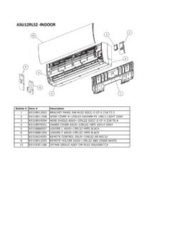
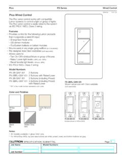
1 WIRED REMOTE CONTROLLER (Optional parts)MODEL NAME :UT Y- RV N Zone CONTROLLER functions using this REMOTE CONTROLLER , refer to "ZONE CONTROL SYSTEM (DTR_OP006E)".- (OP005 - 01) - WIRED REMOTE CONTROLLERWIRED REMOTE CONTROLLERFE ATURES11 MODEL UT Y- RV N M, UTY-RVNYNL arge and full-dot liquid crystal screen Screen with backlight can be seen even in the dark Wide and large keys easy to press, user-intuitive arrow key ModeMenuCoolMonitorSet F80 Mo 10:00 AMIcon check: Temperature unit [ C]Temperature unit [ F]FE ATURES Group & Individual Control zUp to 16 indoor units can be simultaneously controlled. CONTROLLER is two installation possibility in one indoor unit. And CONTROLLER up to two installation possibility per group operation zLarge backlight LED screen Large easy-to-see operation panel Multiple Language Supporting (English, German, French, Spanish, Russian, Portuguese, Italian, Greek, and Turkish)- (OP005 - 02) - WIRED REMOTE CONTROLLERWIRED REMOTE CONTROLLERMAIN FUNCTIONS Auto off timer zThe indoor unit automatically turns off after a set time has time interval for which auto off works can be ) At interval time hour (17:00 to 24:00) to prevent forgetting to turn offSet interval time hour (17:00 to 24:00)Set off time (30 to 240 minutes)17:0024:00 ONAuto OFFOFFSet temperature auto return zThe setting temperature automatically returns to the previous setting time range in which the set temperature can be changed is 10 to 120 operation2422 Set temperature changeAuto return11:4013:40 TimeSettable time range10 to 120 minutesSetting operationSet temperature changeAuto return11:4013.
2 40 TimeSettable time range10 to 120 minutes( C)7672( F)2523( C)7874( F)Set temperature upper and lower limit setting zThe set temperature range can be set for each operation mode.(Cooling / Heating / Auto)Original rangeLower limitsettingDuring Cooling302518 Original rangeUpper limitsettingDuring Heating( C)887864( F)302516( C)887860( F)- (OP005 - 03) - WIRED REMOTE CONTROLLERWIRED REMOTE CONTROLLERW eekly timer function zNot only time setting On/Off, but also setting of the operation mode and set temperature can be set by Weekly timer function. Two types of setting: Weekly 1 and Weekly 2 for summer and winter are 1 Set ( F)( C)202122232425 Set ( F)( C)20212223242510:0022 C12:0014:0017:0020:0023:59 Setting menu in REMOTE controllerOnOffWeekly 2 Time10:0012:0014:0017:0020:0023:59 Setting menu in REMOTE controllerOnOffWeekly 1 Set ( F)( C)202122232425 Set ( F)( C)20212223242510:0022 C12:0014:0017:0020:0023:59 Setting menu in REMOTE controllerOnOffWeekly 2 Time10:0012:0014:0017:0020:0023:59 Setting menu in REMOTE controllerOnOffChild lock zThis function locks all control.
3 Part lock zThis function locks the setting of functions other than Mode, Set temp., (Pass word) zUnwanted functions can be restricted. Password is necessary to operate. Functions with this mark are (OP005 - 04) - WIRED REMOTE CONTROLLERWIRED REMOTE CONTROLLERFUNCTION LIST It's shown below function of UTY-RVN M / UTY-RVNYN, UTY-RNN M / UTY-RNNYN and mixture used in mixture, set the UTY-RVN M to Primary unit, and set the UTY-RNN M to Secondary Y- RVN M UTY-RVNYNUT Y- RNN M UTY-RNNYNM ixture use of UT Y- RVN M UTY-RVNYN and UT Y- RNN M UTY-RNNYNA irconditioning controll functionOn / Off Operation mode setting Fan speed setting Set temp. setting Set temp. range limitation - Test run Vertical air flow direction setting Horizontal air flow direction setting Group setting *1 Economy setting Set temp. auto return - DisplayFailure Defrosting Current time Day of week prohibition Address display - Room temp - Multi language - Summer time - Filter sign Backlight - TimerSchedule timerPeriodWeekWeekWeekOn/off, Temp, mode, time, per day8 24 (On/off,time, per day)8 2On/off timer Auto off timer *2 - Day off Min.
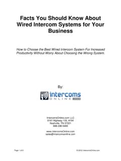
4 Unit of timer setting (Minutes) *310 303010 30 ControlError history REMOTE CONTROLLER sensor control Key lock Operation mode exemption -ProhibitedManagement (Pass word) -Prohibited*1: Can be connected to the system forming a REMOTE CONTROLLER group. *2: Counting down of the Auto-off timer is valid only if the air conditioning operation has been started with the [On/Off button] of this REMOTE CONTROLLER .*3: On/off timer can be set in 30 minutes increments. Auto off timer and Set temp. auto return can be also set in 10 minutes increments. - (OP005 - 05) - WIRED REMOTE CONTROLLERWIRED REMOTE CONTROLLERFUNCTIONS21 1268734591 Display panel (with backlight)2 Screen switch button (Left)3 Menu button4 Cancel button5 Cursor button6 Screen switch button (Right)7 Power indicator8 On / Off button9 Enter button- (OP005 - 06) - WIRED REMOTE CONTROLLERWIRED REMOTE CONTROLLERSPECIFICATIONS31 SPECIFICATIONS Dimensions [H x W x D]: mm (in.)120 (4-23/32) x 120 (4-23/32) x (27/32)Weight: g (oz.)
5 220 ( )WIRING SPECIFICATIONS UseCable sizeWire typeRemarksRemote CONTROLLER mm2 ( 22 AWG )Polar 3 coreUT Y- RVN MUse sheathed PVC shielded cable (field supplied) inaccordance with the regional cable (OP005 - 07) - WIRED REMOTE CONTROLLERWIRED REMOTE CONTROLLERDIMENSIONS41 120 (4-23/32)120 (4-23/32) (27/32)30(1-3/16) (1-25/32) (1/2) (3/16) (3/16) (19/32) (2-1/2) (3-9/32)23(29/32)9 (11/32) (3/16) (1-5/16)Front ViewSide ViewRear ViewUnit : mm (in.)- (OP005 - 08) - WIRED REMOTE CONTROLLERWIRED REMOTE CONTROLLERWIRING DESIGN51 SYSTEM DIAGRAM 1 REMOTE CONTROLLER zz2 REMOTE controllersPrimarySecon-daryABCI ndoor unitIndoor unitRemote controllerRemote controllersA , B , C : REMOTE CONTROLLER cable. ELECTRICAL WIRING 1 REMOTE CONTROLLER zz2 REMOTE controllersIndoor unitREMOTECONTROLLER123123 PrimarySecondaryIndoor unit123123123 REMOTECONTROLLERR emote controllerRemote controllers1. 12V (Red)2. Signal (White)3. COM (Black)Junction box (field supply) CONTROLLER COMBINATION As for the combined usage of the CONTROLLER , refer to following zzProhibitedUTY-RVN MUTY-RVNYNUTY-RNN MUTY-RNNYNUTY-RNBYUUTB- UDUTY-RVN MUTY-RVNYNUTY-RSN MUTY-RVN MUTY-RVNYNUTB- UBUTY-RVN MUTY-RVNYNUTY-RVN MUTY-RVNYNSET unitIndoor unitIndoor unitIndoor unitREMOTE CONTROLLER GROUP CONTROL 1 or 2- REMOTE controllers can simultaneously control up to 16 indoor examples zRemote CONTROLLER cable- (OP005 - 09) - WIRED REMOTE CONTROLLERWIRED REMOTE CONTROLLERINSTALL ATI ON61 1) Installation (8-21/32) ormore*Unit : mm (in.
6 30 (1-3/16)or more30 (1-3/16)or more30 (1-3/16)or more* Please secure enough space where a flat screwdriver to take off a case can be ) Processing of the REMOTE CONTROLLER (5/16)8 (5/16)8 (5/16)30 (1-3/16)45 (1-25/32)55 (2-5/32)Unit : mm (in.)1. 12V (Red)2. Signal (White)3. COM (Black)For UTY-RVNYNFix the near end of the Tube with the cable tie (large) firmly. Do not fix the functional earthing wire with the cable tie (large).Connect the functional earthing wire of REMOTE CONTROLLER and the REMOTE CONTROLLER cable, and perform the ) Insert the flat-blade screwdriver and remove the front case and rear case by twisting it (OP005 - 10) - WIRED REMOTE CONTROLLERWIRED REMOTE CONTROLLER4) Installing the REMOTE controllerA1 When attaching to switch box:(1) Seal the wiring hole of the REMOTE CONTROLLER cable.(2) Put a REMOTE CONTROLLER cable through the hole of the rear case.(3) Fix the rear case by securing it with attached screws (2 places).B1 When attaching to the wall directly:(1) Seal the wiring hole of the REMOTE CONTROLLER cable.
7 (2) Put a REMOTE CONTROLLER cable through the back hole of the rear case of the main body.(3) Fix the rear case by securing it with attached screws (2 places).C1 When routing the cable on-wall:(1) Cut off the cable guide of the front case with using a knife or a nipper.(2) Deburr the edge of the cable guide.(3) Fix the rear case by securing it with attached screws (2 places).- (OP005 - 11) - WIRED REMOTE CONTROLLERWIRED REMOTE CONTROLLER5) Connect the cable to the terminals on the front case. Fix the cable together with the sheath with the cable tie. Cut off the excess cable torqueTerminal to m (8 to 12 lbf in)1. 12V (Red)2. Signal (White)3. COM (Black)Cable tie(small) REMOTE CONTROLLER cable (sheath)Hole for cable tie2 mm (3/32 in)GOODPROHIBITEDTo avoid an excessive tension or pressure to the terminal block, fix the REMOTE CONTROLLER cable with the cable tie properly. CAUTIONBe careful to avoid breaking the cable by over-tightening the cable tie. When connecting the REMOTE CONTROLLER cables, do not over-tighten the screws.
8 6) Attach the front after adjusting upper part of front case. When insert the front case, do not pinch the cable. Front caseGoodClick!No goodNo goodNo goodPROHIBITEDGOOD CAUTIONI nsert the upper case firmly. If improperly attached, it will cause the upper case to fall off. - (OP005 - 12) - WIRED REMOTE CONTROLLERWIRED REMOTE CONTROLLERFUNCTION SETTING71 SWITCH SETTING7-11 DIP SwitchSW1 Memory backup settingSW2 Dual REMOTE CONTROLLER setting Switch position z DIP Switch setting zMemory backup setting Set to ON to use batteries for the memory batteries are not used, all of settings stored in memory will be deleted if there is a power failure.( setting)SW1 Memory backupuOFFI nvalidityONValidityDual REMOTE CONTROLLER setting Set the REMOTE CONTROLLER SW2 according to the following table.( setting)Number of REMOTE controllerPrimary unitSecondary unitSW2SW2u1 (Normal)OFF-2 (Dual)OFFON12 312 3123 Indoor unitRemote CONTROLLER cablePrimary unitSecondary unitRemote controllerJunction box (field supply)- (OP005 - 13) - WIRED REMOTE CONTROLLERWIRED REMOTE CONTROLLERINDOOR UNIT (setting by CONTROLLER )7-21 Function setting for indoor unit can be done by using the REMOTE CONTROLLER .
9 As for the "FUNCTION SETTING", refer to the DESIGN & TECHNICAL MANUAL for each ) When [Menu button] is pressed twice while Monitor screen is displayed, it switches to the Submenu screen. If [Menu button] is pressed while the Submenu screen is displayed, the display returns to the Monitor :Setting:Date and timeSubmenu [1/2]MonitorScreenFilter sensor controlRoom temp. displayOffOffMo 10:002) Press the [Screen switch button (Left)] and [Screen switch button (Right)] simultaneously for 5 seconds to switch to Service Setting: Service Mo 10:00 Function settingError verificationVersionTest run3) Select [Function setting] with pressing the [Cursor button (Up/Down)], and press the [Enter button].Back: Setting: Service Mo 10:00 Function settingError verificationVersionTest run4) Select [ address] of the target indoor unit with pressing the [Cursor button (Up/Down)].
10 ( Address : REMOTE CONTROLLER Address)Cancel: OK: Function setting Mo 10:00 Function Setting address No. 00 00 Version Error history5) Select the [Function No.] with pressing the [Cursor button (Left/Right)], and select the Function No. to be set with pressing the [Cursor button (Up/Down)].Cancel: OK: Function setting Mo 10:00 Function Setting address No. No. Version Error history00 00 006) Select the [Setting No.] with pressing the [Cursor button (Left/Right)], and select the Setting No. to be set with pressing the [Cursor button (Up/Down)],and press the [Enter button].Cancel: OK: Function setting Mo 10:00 Function Setting address No.